Elastic body coarse and intermediate crushing crusher
A pulverizer, elastomer technology, applied in recycling technology, grain processing, plastic recycling, etc., can solve problems such as high noise
- Summary
- Abstract
- Description
- Claims
- Application Information
AI Technical Summary
Problems solved by technology
Method used
Image
Examples
Embodiment 1
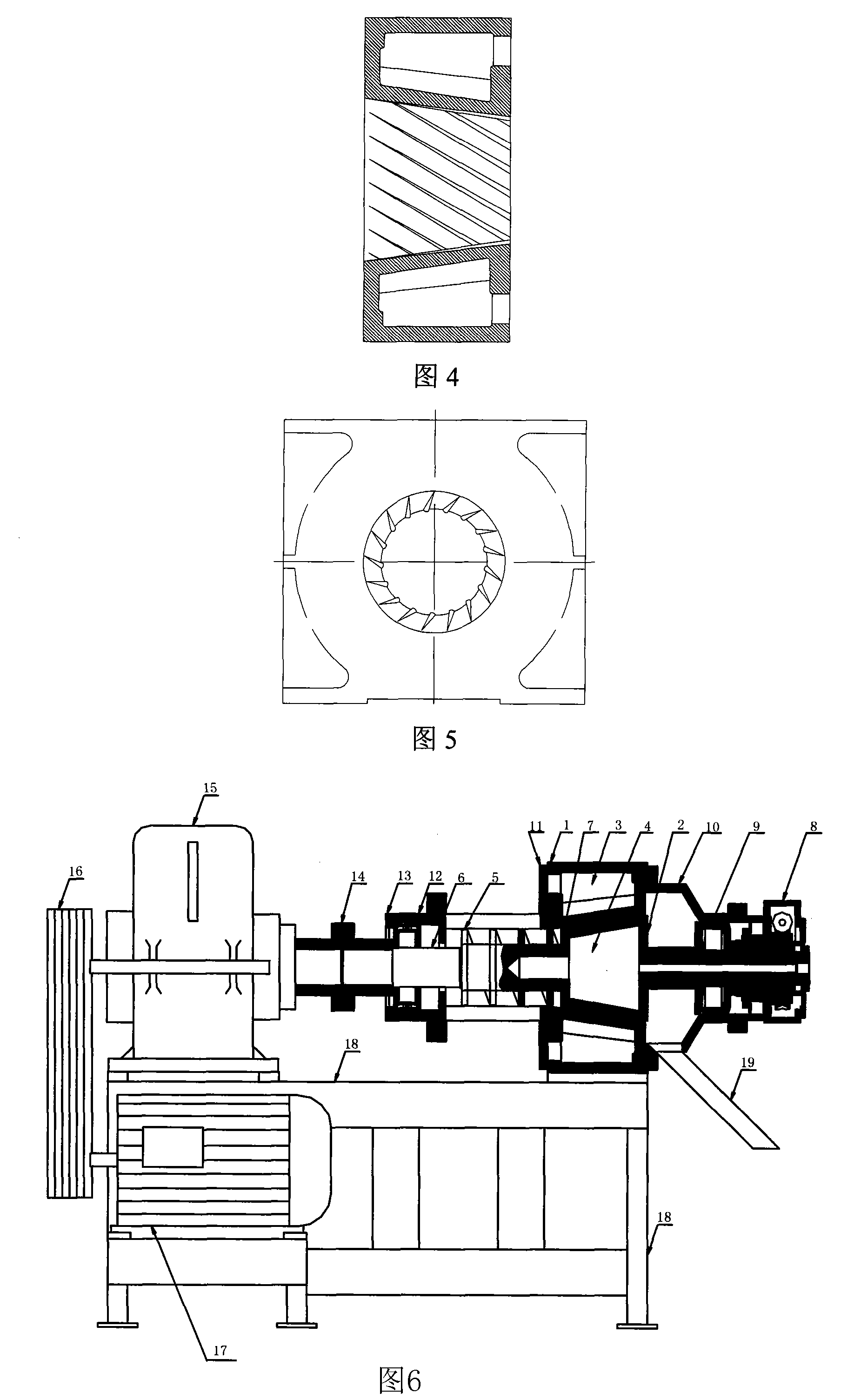
[0037] A cone grinding disc used in high-efficiency pulverizers for coarse and medium crushing of elastomers, as shown in Figure 1, as shown in the figure: 1 is the static grinding stator in the cone grinding disc, and 2 is the dynamic grinding rotor in the cone grinding disc , 3 is the water cooling cavity in the fixed mill, 4 is the water cooling cavity in the moving mill, 5 is the feeding thread with a notch, 6 is the transmission shaft, 7 is the working surface of the table cone grinding disc with grooves , D is the nominal diameter of the dynamic grinding cone, H is the nominal height of the dynamic grinding cone, and α is the angle between the working surface of the table cone grinding disc.
[0038] As shown in Figure 1, the nominal diameter D of the table cone bottom of the dynamic grinding rotor can be in the range of 200-550mm, the nominal height H of the table cone of the dynamic grinding rotor can be in the range of 100-500mm, and the cone surface clip of the dynami...
Embodiment 2
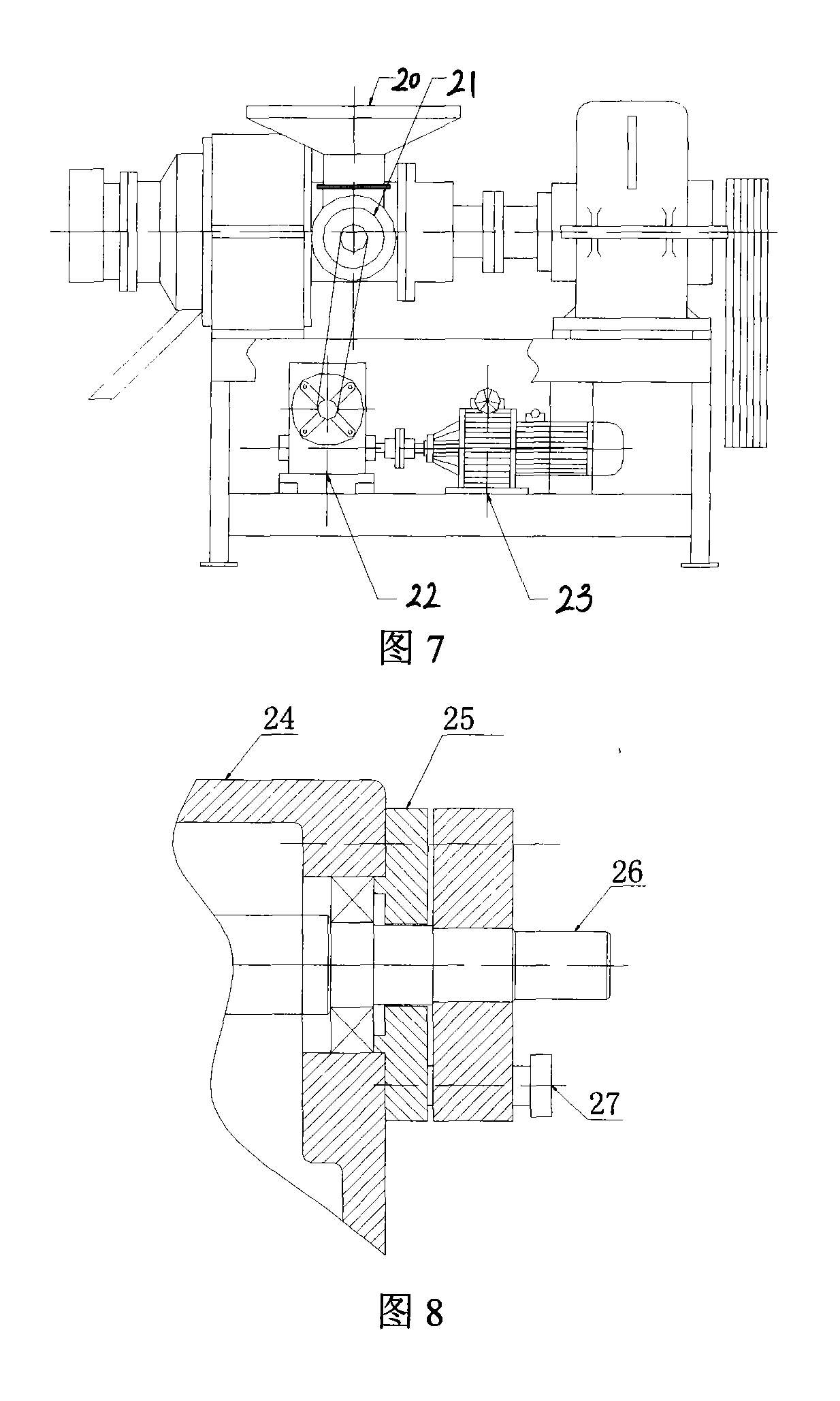
[0043] The structure diagram of the complete coarse and medium crushing machine is shown in Figure 6: Among them, 2 is the movable mill rotor in the table cone grinding disc, 3 is the water cooling cavity in the fixed mill, and 4 is the water cooling hole in the dynamic mill Cavity, 5 is the feeding thread with notch, 6 is the transmission shaft, 7 is the working surface of the table cone grinding disc with groove groove, 8 is the worm gear device for adjusting the gap of the working surface, 9 is the bearing seat, 10 is the discharge hole Cavity casing, 11 is the feeding cavity, 12 is the bearing seat, 13 is the limit mechanism, 14 is the coupling, 15 is the reducer, 16 is the transmission belt, 17 is the motor, 18 is the frame, 19 is the discharge road board.
[0044] In the pulverizer of the prior art, when the working surfaces of the moving grinding rotor and the static grinding stator are in contact with each other, the end of the main bearing is just in contact with the ...
Embodiment 3
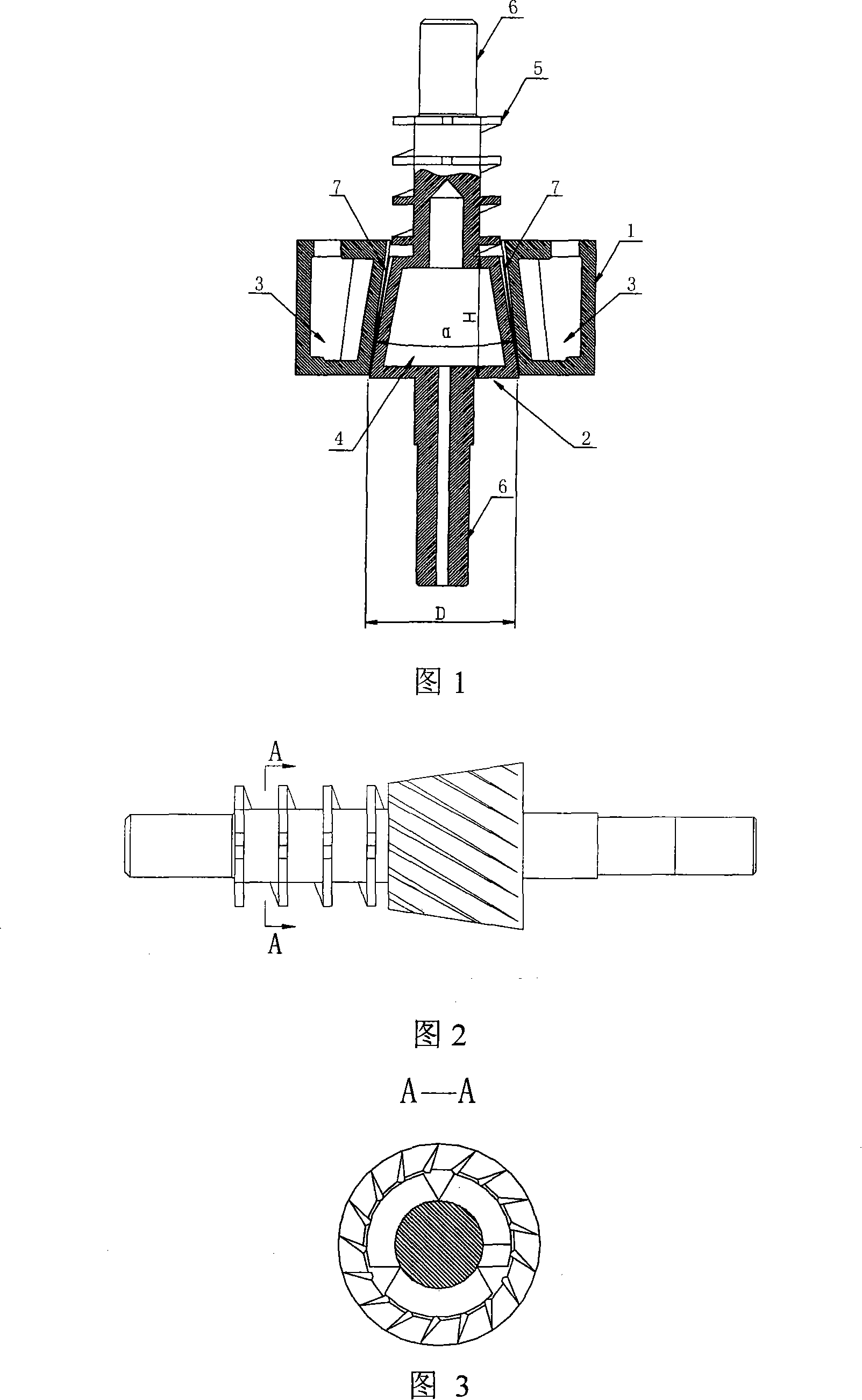
[0048] The schematic diagram of Fig. 8 demonstrates a locking structure arranged on the worm wheel of the pulverizer, wherein: 24 is the worm gear box, 25 is the bearing cover, 26 is the worm, and 27 is the locking mechanism. The worm 26 adjusts the relative rotational speed between the dynamic grinding rotor and the static grinding stator by adjusting the gear of the worm gear case 24 . In the prior art, due to the high vibration intensity during the working process of the pulverizer, it is easy to make the adjustment position of the worm deviate. The present inventor has provided a locking mechanism 27 on the bearing through cover 25 of the worm gear case 24, and the locking mechanism 27 can position and lock the gears inside the worm gear case 24, so as to accurately control the relationship between the dynamic grinding rotor and the static grinding stator. The technical effect of the relative rotational speed between them. Of course, according to actual needs, other parts...
PUM
| Property | Measurement | Unit |
|---|---|---|
| Rockwell hardness | aaaaa | aaaaa |
| diameter | aaaaa | aaaaa |
| hardness | aaaaa | aaaaa |
Abstract
Description
Claims
Application Information
 - R&D
- Intellectual Property
- Life Sciences
- Materials
- Tech Scout
- Unparalleled Data Quality
- Higher Quality Content
- 60% Fewer Hallucinations
Browse by: Latest US Patents, China's latest patents, Technical Efficacy Thesaurus, Application Domain, Technology Topic, Popular Technical Reports.
© 2025 PatSnap. All rights reserved.Legal|Privacy policy|Modern Slavery Act Transparency Statement|Sitemap|About US| Contact US: help@patsnap.com


