Battery can and method of manufacturing the same
A manufacturing method and technology of battery cans, which are applied to lithium batteries, battery pack parts, battery boxes/coatings, etc., can solve problems such as being vulnerable to damage, and achieve the effect of ensuring strength
- Summary
- Abstract
- Description
- Claims
- Application Information
AI Technical Summary
Problems solved by technology
Method used
Image

Examples
Embodiment 1
[0052] The battery can of the present invention was produced according to the method of producing the battery can of the present invention described in the above embodiments. Specifically, the battery can of the present invention was produced in the following manner.
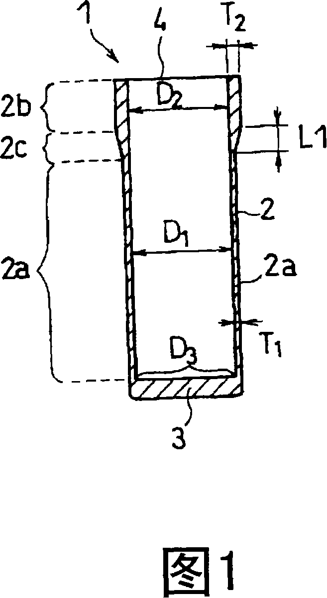
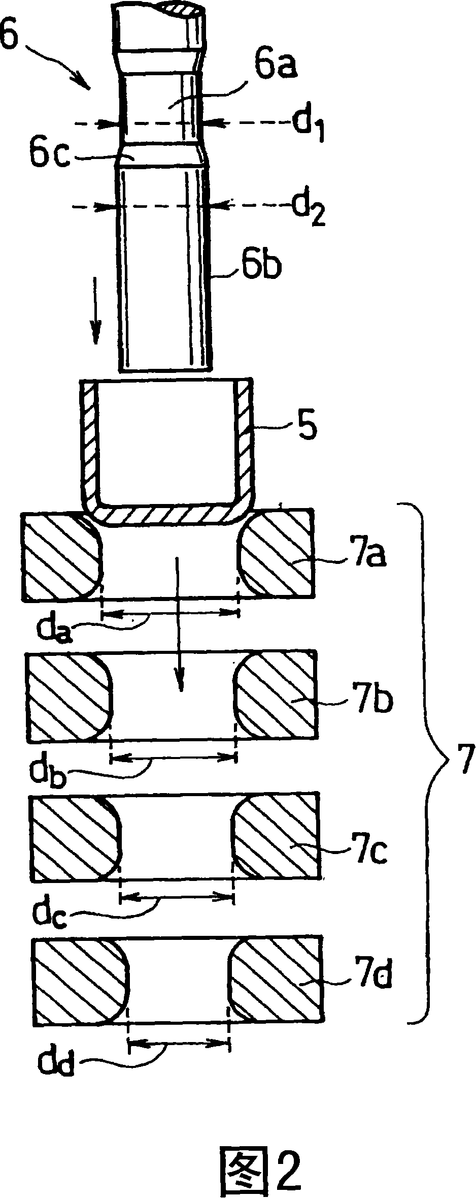
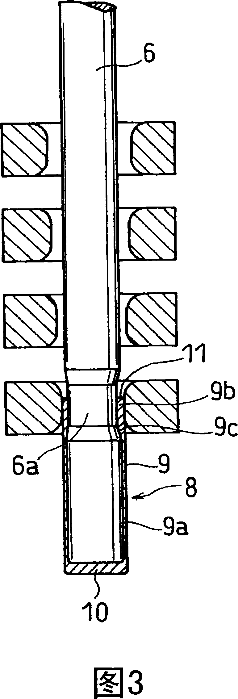
[0053] The nickel-plated steel sheet was punched out into a circular shape, and the nickel-plated steel sheet was drawn so that the inner side was formed, thereby obtaining a can base material composed of a bottomed cylindrical body. Using a forming die and a forming punch having the structure shown in Figure 2, the obtained tank base material made of a cylindrical body with a bottom is subjected to a DI process (step (1)), and formed into a cylindrical shape, thereby obtaining the tank base material having the shape shown in Figure 4 Intermediate product 8 of the structure shown.
[0054] Next, in the intermediate product 8 obtained above, insert the flaring punch 12 having the structure shown in FIG. 1 =D 2...
Embodiment 2
[0069] As shown in Table 2, by changing the length L of the boundary portion from the first side side to the second side side 1 while making {L 1 / (T 2 -T 1 )} were changed in various ways, and battery cans A to D were produced in the same manner as in Example 1.
[0070] Table 2
[0071] L1(mm)
{L 1 / (T 2 -T 1 )}
Battery tank A
2
25
battery tank B
4
50
battery tank C
8
100
battery tank D
10
125
[0072] The lithium ion secondary battery shown in FIG. 6 was manufactured by using battery cans A to D to seal according to the following steps. As the electrode plate group housed in the battery can 21 , an electrode group having a diameter of 17.75 mm was used. The positive electrode plate 25 is electrically connected to the sealing body 22 through the positive electrode lead 25a, and the negative electrode plate 26 is electrically connected to the bottom inn...
Embodiment 3
[0076] As shown in Table 3, the length L in the longitudinal direction of the can base material of the convex part of the flaring punch used when the intermediate product is processed into a battery can by step (2) was changed. 2 , so that (L 3 / L 2 ) was changed in various ways, battery cans E to I were produced in the same manner as in Example 1. Then, the inner diameter D of the second side portion of each battery can was measured 2 and the inner diameter D of the bottom of the battery can 3 . The measurement results are shown in Table 3.
[0077] table 3
[0078] L 2 (mm)
L 3 / L 2
D. 2 (mm)
D. 3 (mm)
Battery tank E
0.12
0.02
17.70
18.00
Battery tank F
0.3
0.05
17.76
18.00
Battery tank G
1.2
0.2
17.76
18.00
Battery tank H
2.4
0.4
17.76
18.00
Battery tank I
3
0....
PUM
| Property | Measurement | Unit |
|---|---|---|
| Length | aaaaa | aaaaa |
| Outer diameter | aaaaa | aaaaa |
| Height | aaaaa | aaaaa |
Abstract
Description
Claims
Application Information
 - Generate Ideas
- Intellectual Property
- Life Sciences
- Materials
- Tech Scout
- Unparalleled Data Quality
- Higher Quality Content
- 60% Fewer Hallucinations
Browse by: Latest US Patents, China's latest patents, Technical Efficacy Thesaurus, Application Domain, Technology Topic, Popular Technical Reports.
© 2025 PatSnap. All rights reserved.Legal|Privacy policy|Modern Slavery Act Transparency Statement|Sitemap|About US| Contact US: help@patsnap.com