Fuel supply device

A fuel supply device and fuel technology, applied in the direction of liquid fuel feeder, charging system, combustion engine, etc., can solve the problems of torque loss in the sealing part, fuel leakage, motor enlargement, etc., to achieve the prevention of rising and reliability Higher effect

Inactive Publication Date: 2008-06-25
MITSUBISHI ELECTRIC CORP
View PDF1 Cites 8 Cited by
  • Summary
  • Abstract
  • Description
  • Claims
  • Application Information

AI Technical Summary

Problems solved by technology

However, at this time, if the seal part is damaged or deteriorated, fuel will leak to the outside, and there is also a problem of torque loss in the seal part, complicating the structure, and increasing the size of the motor.

Method used


Image

  • Fuel supply device
  • Fuel supply device

Examples


Embodiment Construction

[0025] Embodiment 1

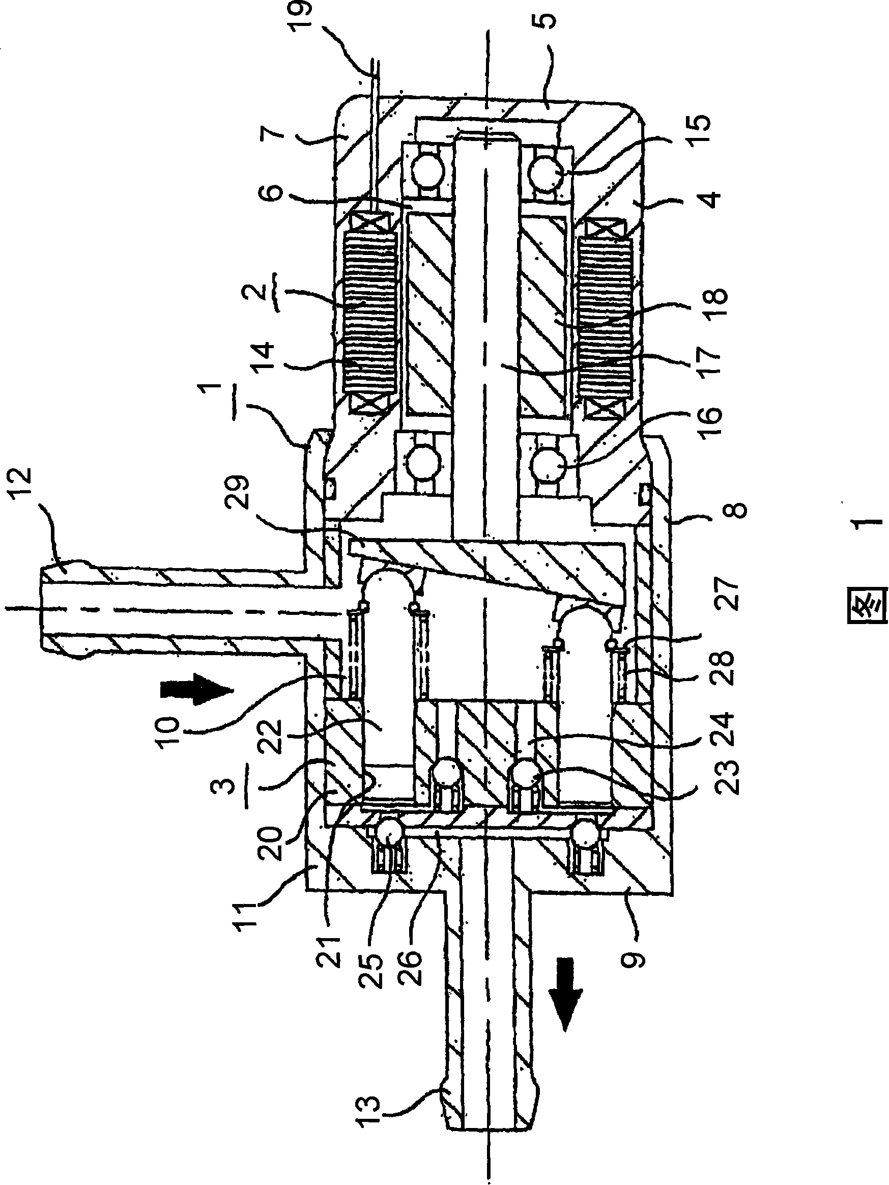
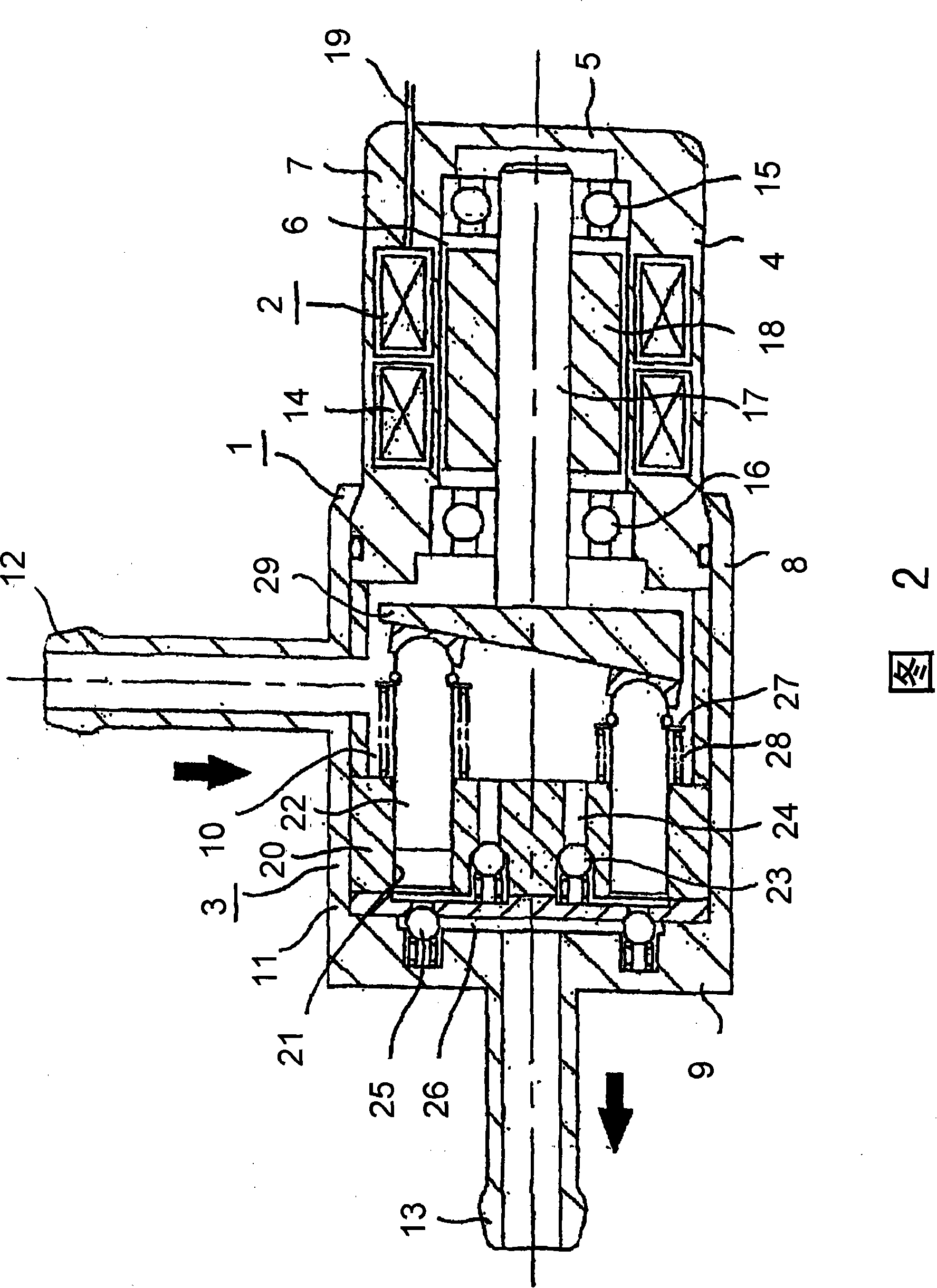
[0026] The fuel supply device of the present invention shown in Fig. 1 comprises: the shell 1 that is generally hollow cylinder as a whole; The electric motor 2 that is arranged in the shell 1; .

[0027] Housing 1 comprises: motor housing 7, has cylindrical wall 4 and end wall 5 as housing wall, is formed with the motor chamber 6 that accommodates motor 2 inside; And pump device housing 11, pump device housing 11 has The cylindrical wall 8 and the end wall 9 form a pump device chamber 10 in which the pump device 3 is accommodated. The open end of the pump housing 11 is firmly connected to the open end of the motor housing 7 by riveting or the like, and the motor chamber 6 and the pump chamber 10 communicate with each other. A fuel inlet 12 is provided on the cylindrical wall 8 of the pump device housing 11 , and a fuel outlet 13 is provided on the end wall 9 . The motor casing 7 is closed except that the open end communicates with the pump device casi...


PUM


Abstract

The present invention provides a highly credible fuel supplying device preventing fuel temperature ascend. The fuel supplying device includes a case having a suction inlet, a delivery outlet, a motor chamber and a pump device chamber, the motor chamber are interconnected with the pump device chamber, but the suction inlet and the delivery outlet are directly connected with the pump chamber, fuel sucted from the suction inlet to the pump device chamber is sucted by the pump device on the condition of not passing the motor chamber, and output to the delivery outlet. A motor stator is embedded in the wall of the case. The motor may be brushless motor or stepper motor, processing speed control according to the consumption flow rate of the fuel injection valve. The fuel supplying device prevents the temperature ascend, and improves the credibility.

Description

technical field [0001] The invention relates to a fuel supply device. Background technique [0002] Due to environmental problems, the fuel supply system has been changed from a mechanical carburetor to an electronically controlled system with a fuel injection valve from the viewpoint of exhaust gas restriction and fuel cost increase. In recent years, all automobiles have adopted the latter system. In recent years, the restriction of environmental problems is not only limited to automobiles, but also gradually expanded to two-wheeled vehicles, outboard motors, and special vehicles. Among the fuel supply devices used in automobiles, centrifugal pumps installed in fuel tanks are used. The in-tank type fuel supply device (not shown) has become the mainstream, but because of this, a larger fuel tank is required. Due to the small size of the fuel tank, the small displacement, and the problem of installation space, it is impossible to configure the in-tank type in the fuel tank. ...

Claims


Application Information

Patent Timeline
IPC IPC(8): F04B1/16F02M37/08
CPCY02T10/123Y02T10/12
Inventor 楠本教志大西善彦能濑慎也
Owner MITSUBISHI ELECTRIC CORP
Why Eureka
Try Eureka