
Storage controller having dynamic voltage for regulating super capacitance

A storage controller and memory technology, applied in the direction of data processing power supply, etc., can solve the problems of long battery charging time, data loss, short life expectancy, etc.

Inactive Publication Date: 2008-06-18
DOT HILL SYST
View PDF1 Cites 12 Cited by
  • Summary
  • Abstract
  • Description
  • Claims
  • Application Information

AI Technical Summary

Problems solved by technology

First of all, the battery is undoubtedly a relatively expensive part of the RAID controller
Second, the current battery-related technology also shows that the power that the battery can maintain will begin to weaken after 2 to 3 years, and this life is also shorter than the expected life of the RAID controller
This also increases the cost of the RAID controller
Third, the operating temperature range without compromising battery life and degrading performance is fairly narrow
Fourth, when the battery power is depleted to compensate for the main power shortage, the RAID controller will have to operate in a low-performance write-through cache mode until the battery power is recharged, which takes a long time to recharge the battery. long
Fifth, when the capacity of the cache memory increases, similarly, the required battery power to compensate for the main power outage also increases relatively; if the required power is regarded as the battery power density, when the demanded power increases The size of the battery will also increase relatively and may even exceed the battery storage space provided on the RAID controller
Therefore, purely using real-time clock techniques for monitoring battery life with capacitors is not suitable in many applications, because the variable life of the capacitors also poses an unacceptable risk of data loss for write caching memory controllers

Method used

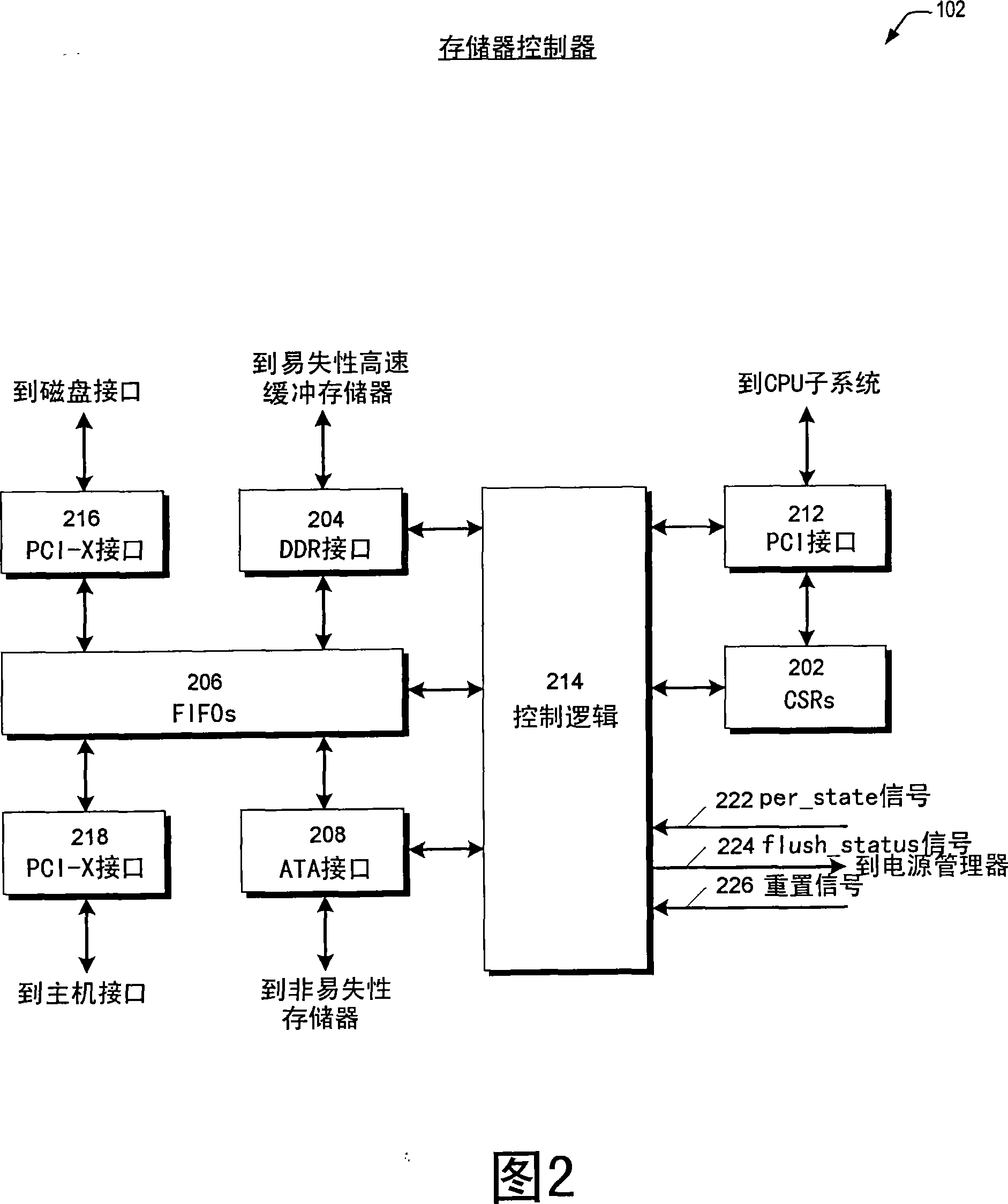
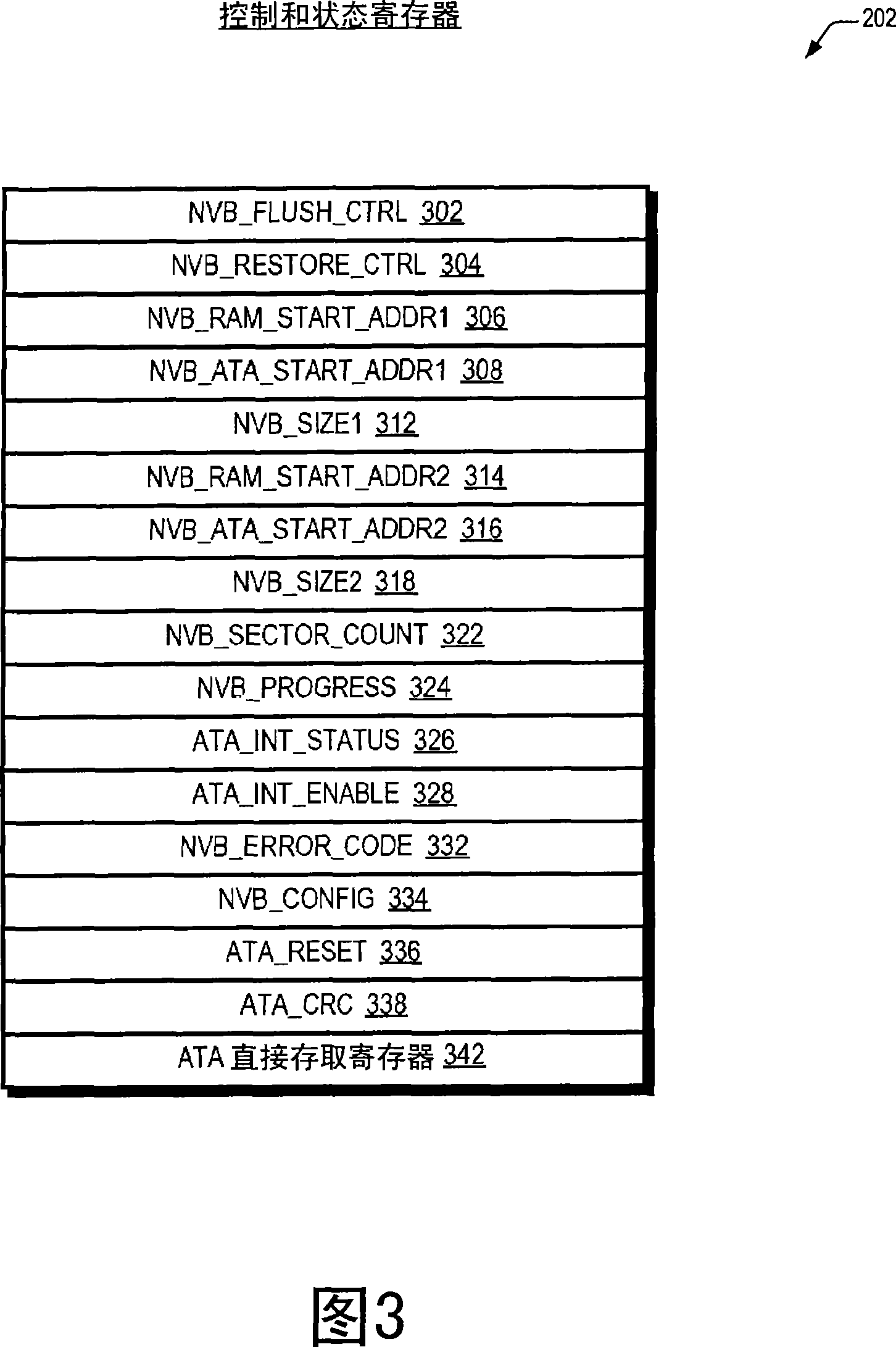

Image

  • Storage controller having dynamic voltage for regulating super capacitance
  • Storage controller having dynamic voltage for regulating super capacitance
  • Storage controller having dynamic voltage for regulating super capacitance

Examples


Embodiment Construction

[0038] Referring now to FIG. 1, there is shown a block diagram of a RAID controller 100 in accordance with the present invention. In one embodiment, RAID controller 100 may be one of a pair of active-active redundant fault-tolerant RAID controllers to provide high data availability. When one RAID controller 100 fails, such as when flushing post-write data from volatile memory to non-volatile memory as described herein, the system will failover to the other RAID controller 100. RAID controller 100 includes one or more capacitors to supply the power required by the circuitry of selected portions of RAID 100 when main power is interrupted, thus enabling the memory controller to quickly and efficiently flush post-write data from the cache memory written to nonvolatile memory. Advantageously, the RAID controller 100 periodically samples the temperature and voltage of the capacitors, and suitably calculates the effective age of the capacitors using lifetime characteristic informat...


PUM


Abstract

A storage controller having a capacitor bank for storing electrical energy to supply electrical energy when a main power source is interrupted, a temperature sensor capable of sensing the temperature of the capacitor bank, and a CPU, the storage controller detecting the capacitor when operating at a first voltage value Whether the temperature of the bank has exceeded a preset threshold, and determine whether the expected life of the capacitor bank is less than the guaranteed life. If the expected lifetime is less than the guaranteed lifetime, the CPU reduces the operating voltage of the capacitor bank to a second value in order to increase the capacitor bank lifetime. In one embodiment, the CPU reduces voltage if the cumulative normalized run time of the capacitor bank is greater than the cumulative calendar run time. In another embodiment, if the capacitance drop percentage of the capacitor bank is greater than the calendar capacitance drop percentage, the CPU reduces the voltage.

Description

[0001] Cross References to Related Applications [0001] This application claims priority to US Provisional Application No. 60 / 705,997, filed August 4, 2005, which is incorporated herein by reference. [0002] This application relates to the following U.S. non-provisional applications: serial number (case number) filing date Invention name (CHAP.0132) Storage controller supercapacitors suitable for lifetime monitoring (CHAP.0136) Dynamically adjust write cache based on super capacitor capacity memory controller size technical field [0003] The present invention relates generally to the field of using capacitor banks as a rechargeable back-up energy supply in memory controllers, and more particularly, the present invention relates to the increased possibility of providing a guaranteed lifetime of capacitor banks. Background technique [0004] Redundant Array of InexpensiveDisk (RAID) system has become ...

Claims


Application Information

Patent Timeline
IPC IPC(8): G06F1/30
Inventor V·K·佩科尼Y·F·王
Owner DOT HILL SYST
Learn More