Bipolar battery and method of manufacturing the same
A bipolar battery and manufacturing method technology, applied in secondary battery manufacturing, secondary battery, nano-battery and other directions, can solve the problems of residual air bubbles, inability to fully remove air bubbles, reduce output, etc. excellent effect
- Summary
- Abstract
- Description
- Claims
- Application Information
AI Technical Summary
Problems solved by technology
Method used
Image

Examples
no. 1 Embodiment approach
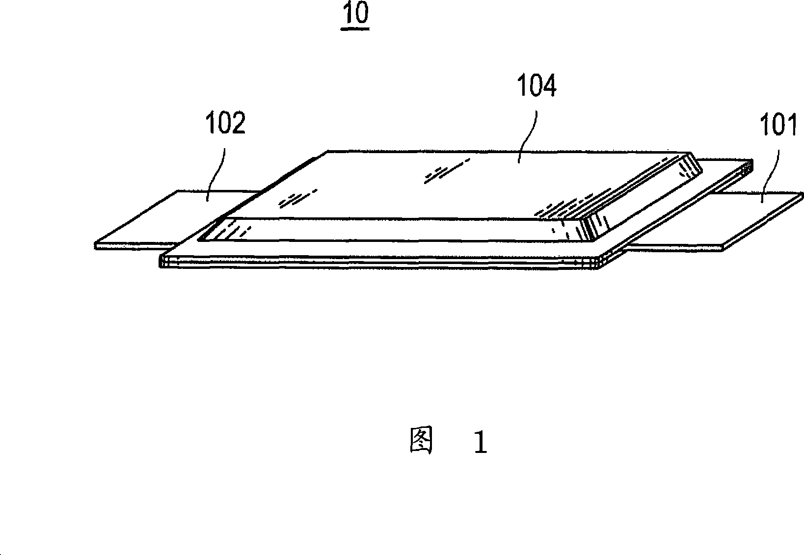
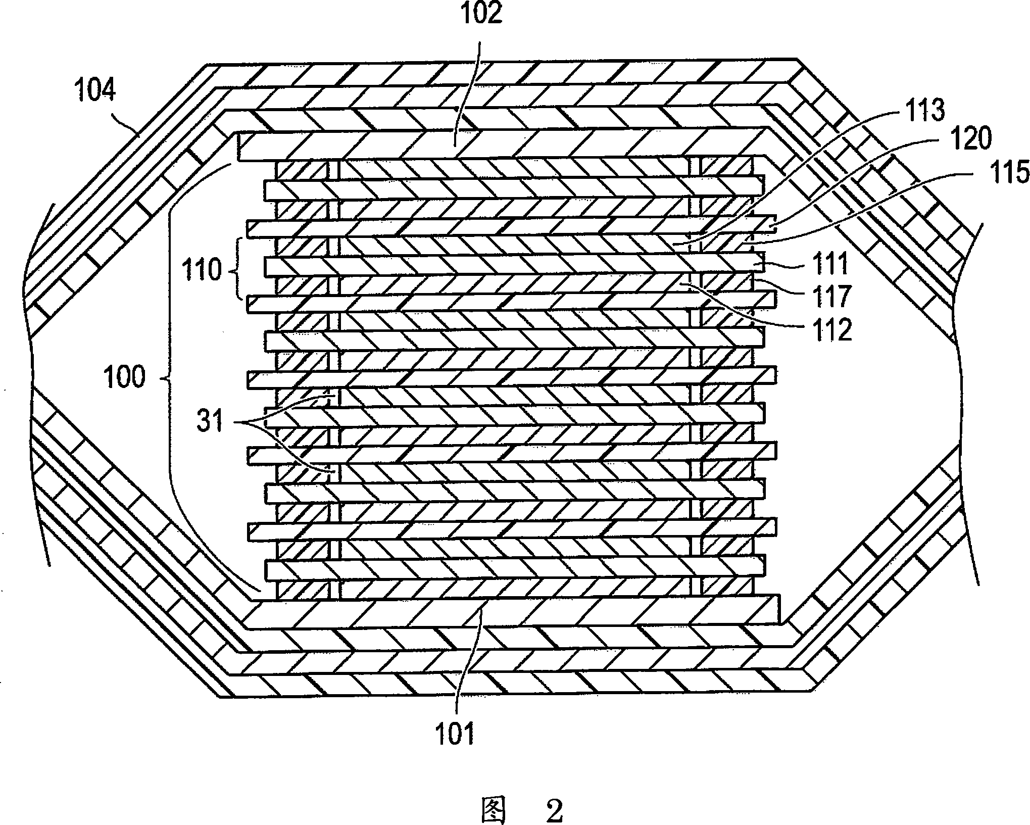
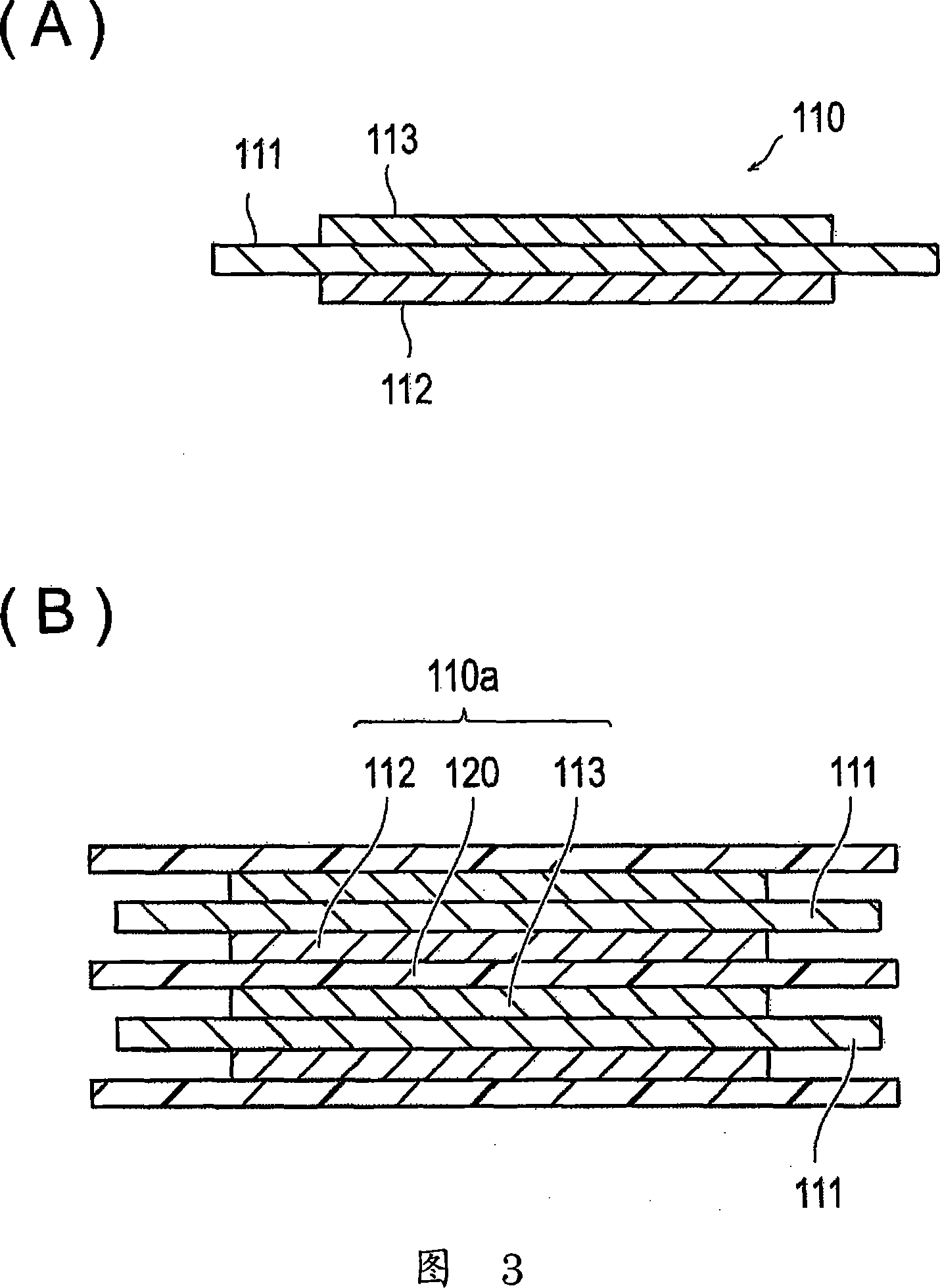
[0071] 1 is a perspective view showing a bipolar battery 10 according to the first embodiment, FIG. 2 is a cross-sectional view showing main parts of the bipolar battery 10, FIG. 3(A) is a cross-sectional view showing a bipolar electrode 110, and FIG. 3( B) is a cross-sectional view for explaining the unit cell layer 110a, FIGS. A plan view of the main part of the bipolar battery 10 according to the first embodiment including the gap 21, FIG. 6 is a plan view showing a state in which the gap 21 is closed, and FIGS. A cross-sectional view of a state where a gas 30 is mixed with the positive electrode 110 and the electrolyte layer 120 . FIG. 8 is a perspective view illustrating a battery pack 130 using the bipolar battery 10 shown in FIG. 1 , and FIG. 9 is a schematic view of a vehicle 138 equipped with the battery pack 130 shown in FIG. 8 .
[0072] Roughly speaking, the bipolar battery 10 of the first embodiment includes a battery element 100 , a filling portion 20 , and a ve...
no. 2 Embodiment approach
[0167] 25(A) and (B) are plan views showing the filling part 20 of the second embodiment in which the material storage parts 22 and 23 are arranged to face the gap part 21 .
[0168] The second embodiment differs from the first embodiment in that it includes material storage parts 22 and 23 for storing the material supplied to the gap part 21 .
[0169] In the second embodiment, the material storage parts 22 and 23 for storing the material supplied to the gap part 21 to close the gap part 21 are arranged so as to face the gap part 21 in the filling part 20 . The material storage portion 22 of FIG. 25(A) has a rectangular shape, and is disposed facing the gap portion 21 away from the application end portion of the sealing material 114 by several dimensions. On the other hand, the material storage part 23 of FIG. 25(B) has a substantially circular shape, and it is arrange|positioned so that the gap part 21 may be formed in connection with the application|coating end part of the ...
no. 3 Embodiment approach
[0172] 26 is a plan view showing main parts of the bipolar battery 10 according to the third embodiment in which the filled portion 20 includes the uncured portion 24, FIG. 27 is a step diagram for explaining the assembly forming step of the third embodiment, and FIG. 28 29 is a diagram showing the state of heating the fillers 114 and 116 by induction heating, and FIG. 30 is a diagram showing the heating of the fillers 114 and 116 by laser heating. A diagram of the case where heating is performed.
[0173] The third embodiment is different from the first and second embodiments in which the vent portion 32 is constituted by the uncured portion 24 .
[0174] Referring to FIG. 26 , the sealing materials 114 and 116 as the filling material of the third embodiment have thermosetting properties, and the filling part 20 includes an uncured part 24 that communicates with the internal space 31 and the outside, and the gas 30 remaining in the internal space 31 is discharged to the outs...
PUM
| Property | Measurement | Unit |
|---|---|---|
| Softening temperature | aaaaa | aaaaa |
Abstract
Description
Claims
Application Information
 - R&D
- Intellectual Property
- Life Sciences
- Materials
- Tech Scout
- Unparalleled Data Quality
- Higher Quality Content
- 60% Fewer Hallucinations
Browse by: Latest US Patents, China's latest patents, Technical Efficacy Thesaurus, Application Domain, Technology Topic, Popular Technical Reports.
© 2025 PatSnap. All rights reserved.Legal|Privacy policy|Modern Slavery Act Transparency Statement|Sitemap|About US| Contact US: help@patsnap.com