
Transactor and paper feeding mechanism therefor

A technology of paper feeding mechanism and business machine, applied in the direction of object separation, pile separation, thin material processing, etc., can solve the problems of unable to provide stable pressure, uneven positive pressure, affecting printing quality, etc.

Inactive Publication Date: 2008-06-18
MICROJET TECH
View PDF0 Cites 0 Cited by
  • Summary
  • Abstract
  • Description
  • Claims
  • Application Information

AI Technical Summary

Problems solved by technology

[0003] The existing paper feeding mechanism mainly uses a paper feeding roller to press on the paper, one side is in contact with the paper and the other side is used to transport the paper in a rotating manner. In order to make the paper feeding mechanism contact with the paper, the axis of the paper feeding roller needs to be Only elastic parts can transmit the pressure to the paper. In other words, the paper feed roller must be a floating roller. However, when the power is transmitted to the paper feed roller through the drive assembly, it is easy to vibrate due to the resistance of the paper feed roller when picking up paper. The positive pressure between the paper feed roller and the paper is uneven, or due to the difference in the thickness of the conveyed paper, it is impossible to provide a stable pressure to each paper. This phenomenon often leads to unstable paper supply. If the paper is skewed or a large amount of paper is taken in at one time, it will easily affect the printing quality or cause paper jams
[0004] Although a paper feed roller fixed on the base has been developed at present, which can indeed achieve the purpose of improving the above-mentioned shortcomings, but after taking off the paper and transferring it to other rollers to drive this kind of fixed paper feed roller, it is necessary to place the paper feed roller on the The load removal in the direction of the paper is to avoid the continuous pressure of the paper feed roller on the paper, which will cause the resistance between the paper and affect the paper feeding state. However, the process of removing the load will affect the stability of the paper feeding.

Method used


Image

  • Transactor and paper feeding mechanism therefor
  • Transactor and paper feeding mechanism therefor
  • Transactor and paper feeding mechanism therefor

Examples


Embodiment Construction

[0021] Some typical embodiments embodying the features and advantages of the present invention will be described in detail in the description in the following paragraphs. It should be understood that the invention is capable of various changes in different aspects without departing from the scope of the invention, and that the description and illustrations therein are illustrative in nature and not limiting. this invention.

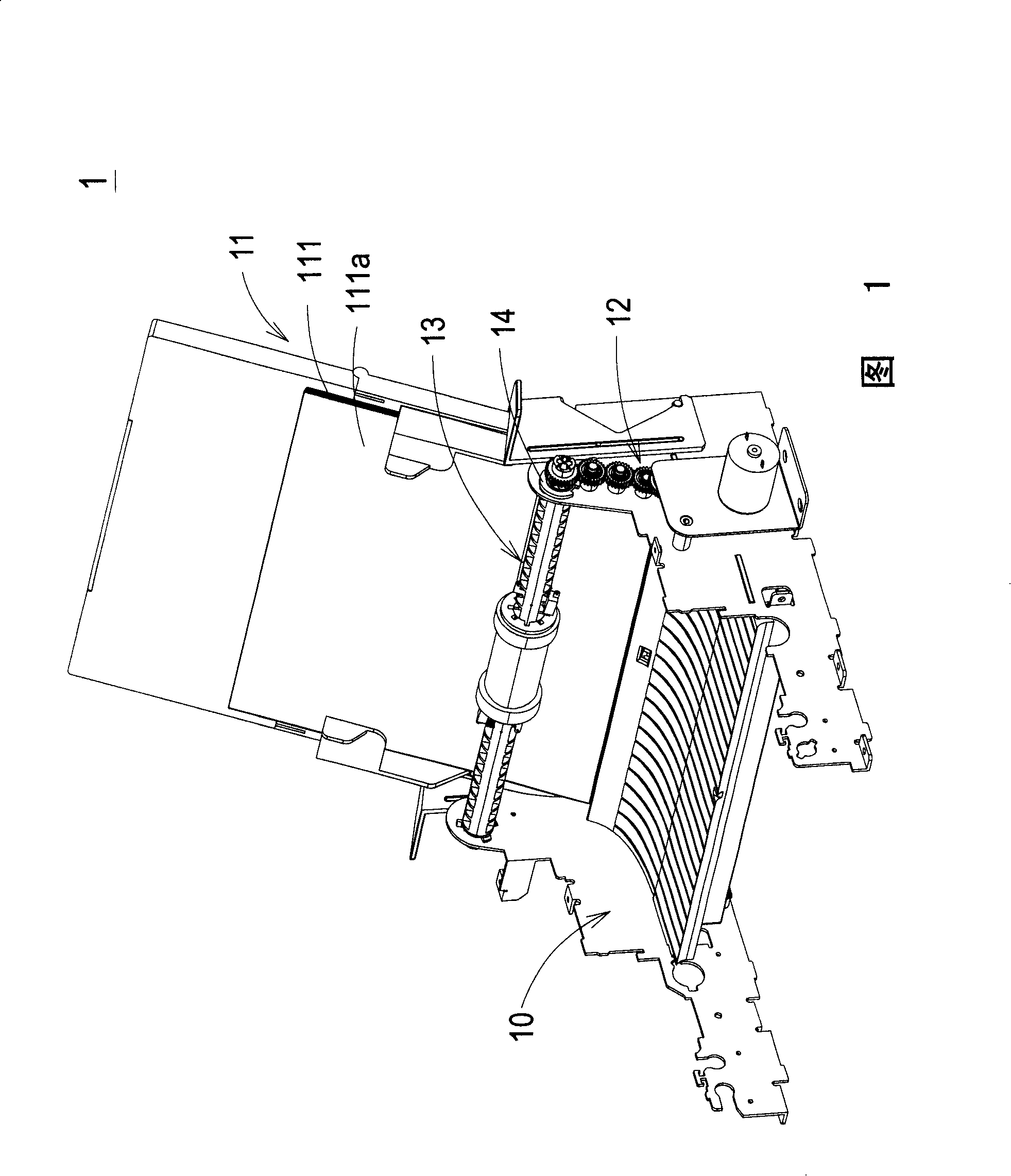
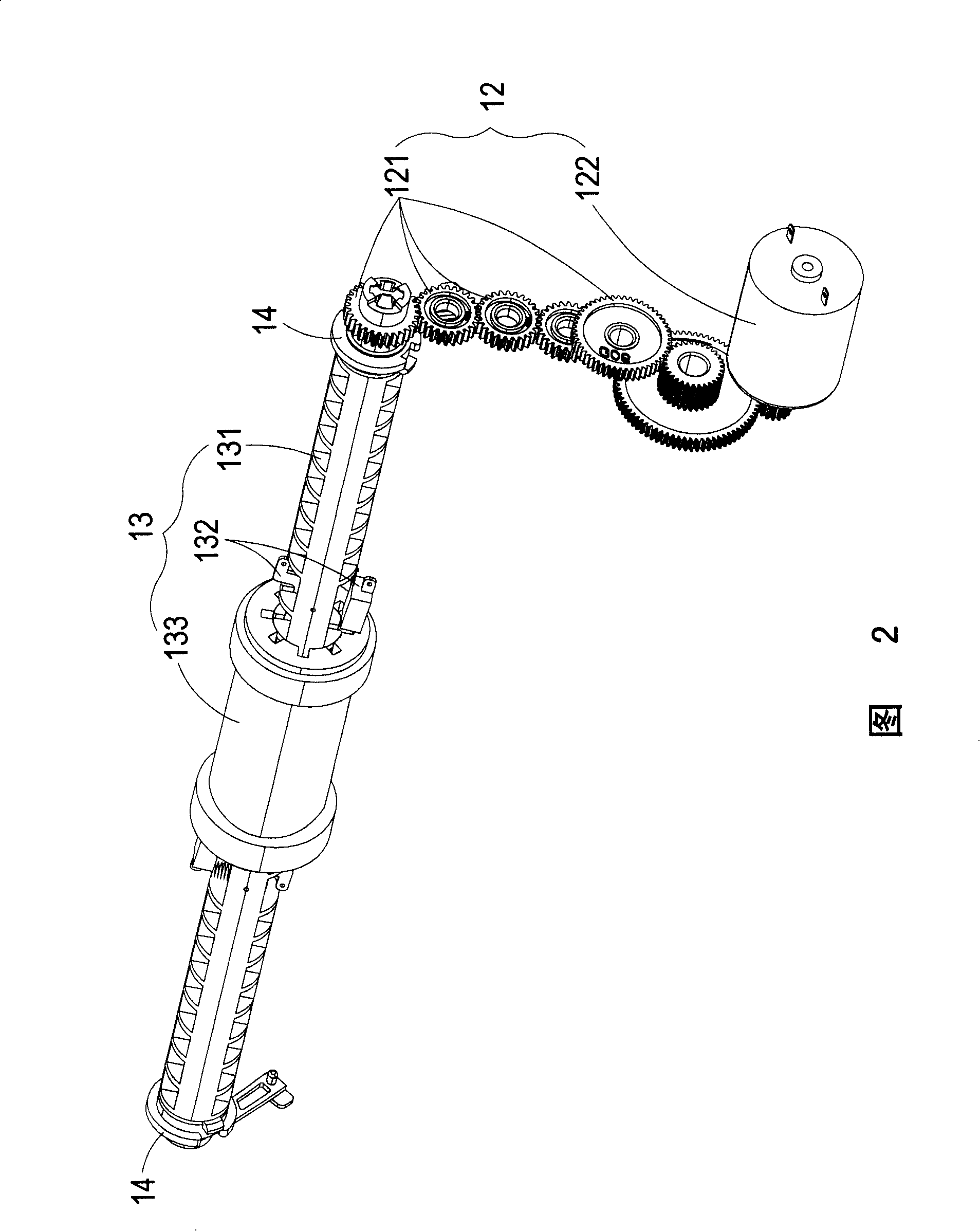
[0022] Please refer to FIG. 1 and FIG. 2 , wherein FIG. 1 is a schematic diagram of the structure of the business machine according to the first preferred embodiment of the present invention, and FIG. 2 is a schematic diagram of the combination of the paper feeding mechanism, the fixing bracket and the drive assembly shown in FIG. 1 . As shown in the figure, the business machine 1 of the present invention includes a main body 10, a bearing base 11, a drive assembly 12 and a paper feeding mechanism 13, wherein the bearing base 11 stands obliquely above the...


PUM


Abstract

The invention relates to a paper feeding mechanism, which is used to guide the paper accommodated in the bearing seat into the printer in order. The paper feeding mechanism comprises a rotating shaft that is provided with an accommodation slot and connected with a driving assembly; a clasp piece that is arranged in the accommodation slot and connected by an elastic component each other; and a paper feeding part that is sleeved on the rotating shaft and corresponding to the clasp piece and also provided with a clasp groove; wherein when the driving assembly drives the rotating shaft to perform the rotation, the elastic component generates deformation correspondingly under the action of the rotating shaft, so that the clasp piece is partially separated from the accommodation slot of the rotating shaft and then clasped in the clasp groove, the paper feeding part is driven by the clasp piece and the rotating shaft to convey the contacted paper into the printer for treatment, when the driving assembly stops driving the rotating shaft, the elastic component draws the clasp piece to separate from the clasp groove, so that the paper feeding part can rotate freely in no need of the driving of the rotating shaft.

Description

technical field [0001] The invention relates to a business machine and its paper feeding mechanism, especially to a business machine and its fixed paper feeding mechanism. Background technique [0002] With the rapid advancement of electronic technology, almost all the office work in today's office is closely related to office machines, such as copiers and printers, etc. These office machines are indispensable information equipment in the office. Usually, general office machines will have Paper mechanism, after the control circuit inside the business machine receives the instruction to start, it will trigger the drive component to transmit power to drive the paper feeding mechanism, so that the paper feeding mechanism will feed the paper into the business machine and send it to other paper rollers for processing Work, after copying, faxing or scanning, etc., the processed paper is sent to the stacking bin at the paper output of the business machine. [0003] The existing pa...

Claims


Application Information

Patent Timeline
IPC IPC(8): B65H3/06
Inventor 萧纪南
Owner MICROJET TECH
Learn More