
Grinding wheel chuck

A technology for chucks and grinding wheels, which is applied to devices for fixing grinding wheels, parts of grinding machine tools, and metal processing equipment. It can solve problems such as insufficient contact rigidity, achieve reasonable positioning, increase cutting force, and expand the application range.

Active Publication Date: 2010-06-09
浙江杭机股份有限公司
View PDF8 Cites 0 Cited by
  • Summary
  • Abstract
  • Description
  • Claims
  • Application Information

AI Technical Summary

Problems solved by technology

The grinding wheel chuck in the prior art uses a large cone as the positioning and main connection part, and its contact rigidity is pressed by a nut on the end face of the cone. If a wider grinding wheel is used or the cutting force increases, the contact rigidity is insufficient.

Method used


Image

  • Grinding wheel chuck
  • Grinding wheel chuck
  • Grinding wheel chuck

Examples


Embodiment

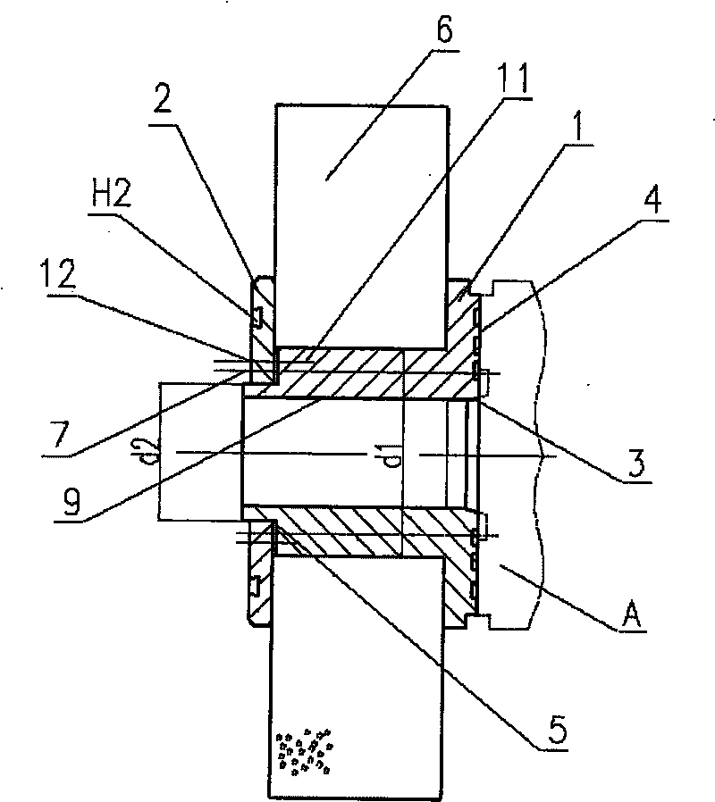
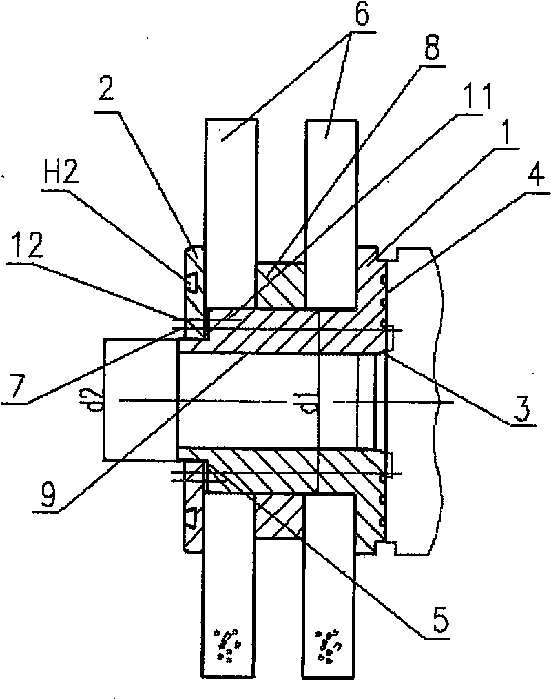
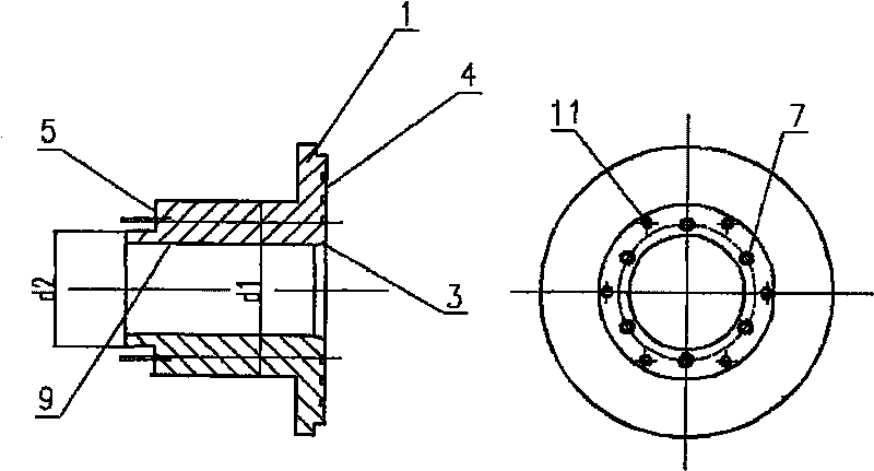
[0015] Such as figure 1 As shown, the grinding wheel chuck is combined by the chuck body 1 and the balance plate 2, and a grinding wheel 6 is housed. The width of the grinding wheel 6 is 100mm. Chuck body 1 (see image 3 Shown) have axial cylindrical inner hole 9 and joint surface 4 protruding from the end face, the inner hole is 65mm, and joint surface 4 has three concentric circular rings with uniform spacing, which is convenient to improve the machining accuracy of the end face. The joint between the joint surface and the inner hole is provided with a short micro-cone 3 that matches the grinding spindle A. The short micro-cone is 15 degrees, and the size of the big end is 70mm. This short micro-cone is positioned and installed on the grinding machine spindle. Convenient and convenient for machining. On the chuck body 1, there are 6 axial countersunk holes 7 fixedly connected with the grinding spindle A by screws and 6 screw holes 11 on the shoulder surface 5 connected wit...


PUM


Abstract

The invention discloses a novel grinding wheel chuck device of a grinder equipment, which is composed of a chuck body and a balance disk. The chuck body comprises an axial column inner hole and a joint surface which protrudes on the end surface and is composed of a plurality of circular rings; the joint part of the joint surface and the inner hole is provided with a short and micro inner cone matched with a grinding main shaft; a plurality of axial counterbore holes which are connected fixedly with the grinding main shaft through a bolt and a plurality of screw holes which are connected with the balance disk are arranged on the chuck body; the balance disk is enclosed on the chuck body and is provided with via holes corresponding to axial via holes on the chuck body and counter bores matched with the screw holes; a coattail type balance ring groove is arranged on the left side surface of the balance disk. Because the joint surface of the large end surface is connected with the end surface of the grinder main shaft directly, the contact rigidity is enhanced and the cutting force is increased. The invention is convenient to install and flexible to be used, so that the working efficiency of a machine tool is increased.

Description

technical field [0001] The invention relates to machine tool equipment for mechanical processing, in particular to a grinding wheel chuck device in the grinding machine equipment. Background technique [0002] The grinding wheel chuck is used to clamp the grinding wheel, which is a necessary tool for grinding processing equipment, especially for grinding machine tools such as plane forming. The grinding wheel chuck of the prior art uses a large cone as the positioning and main connection part, and its contact rigidity is pressed by a nut on the end face of the cone. If a wider grinding wheel is used or the cutting force increases, the contact rigidity appears insufficient. Contents of the invention [0003] The invention mainly solves the shortcomings of the prior art, so as to develop a new type of grinding wheel chuck that can improve the contact bonding force between the grinding wheel chuck and the grinding spindle. [0004] The above-mentioned technical problems of t...

Claims


Application Information

Patent Timeline
Patent Type & Authority Patents(China)
IPC IPC(8): B24B45/00
Inventor 骆广进董凯夫周哲平周昕秦炜
Owner 浙江杭机股份有限公司
Learn More