
Hot drinks machine with distribution mechanism

A technology of dispensing mechanism and hot drink machine, which is applied to household appliances, kitchen appliances, beverage preparation devices, etc., can solve the problems of danger, hot coffee scald, limited death, etc., and achieve the effect of avoiding scalding.

Inactive Publication Date: 2008-06-18
全能电业科技(深圳)有限公司
View PDF1 Cites 11 Cited by
  • Summary
  • Abstract
  • Description
  • Claims
  • Application Information

AI Technical Summary

Problems solved by technology

These novel coffee machines still have defects, for example: a kind of coffee machine disclosed in U.S. Patent No. 6,681,960 B2 is provided with a large-capacity beverage box on the upper front end of the machine, and the dispensing operating mechanism is located at the bottom of the beverage box. Operate the mechanism, and the coffee will flow out of the beverage box. Since the beverage box is set above the base of the machine, the bottom of the beverage box is usually only slightly higher than the cup, and the height of the cup is limited by the beverage box. For example , allows the use of ordinary cups, but does not allow the use of travel cups. To use travel cups, the position of the beverage box must be raised, which requires the entire coffee machine to be made larger
[0004] This steerable dispensing mechanism is convenient for the user to decide the amount of coffee, but the user must hold the cup to keep triggering the operating mechanism before the coffee is filled, so that the coffee can be used in the process of adding coffee to the cup. The operator must pay attention to whether it will overflow, and the controllable dispensing mechanism adopts a mechanical lever mechanism. Hands Potentially Dangerous: Hot Coffee Could Burn It

Method used


Image

  • Hot drinks machine with distribution mechanism
  • Hot drinks machine with distribution mechanism
  • Hot drinks machine with distribution mechanism

Examples


Embodiment Construction

[0024] The present invention will be further described in detail below in conjunction with the preferred embodiments shown in the accompanying drawings.

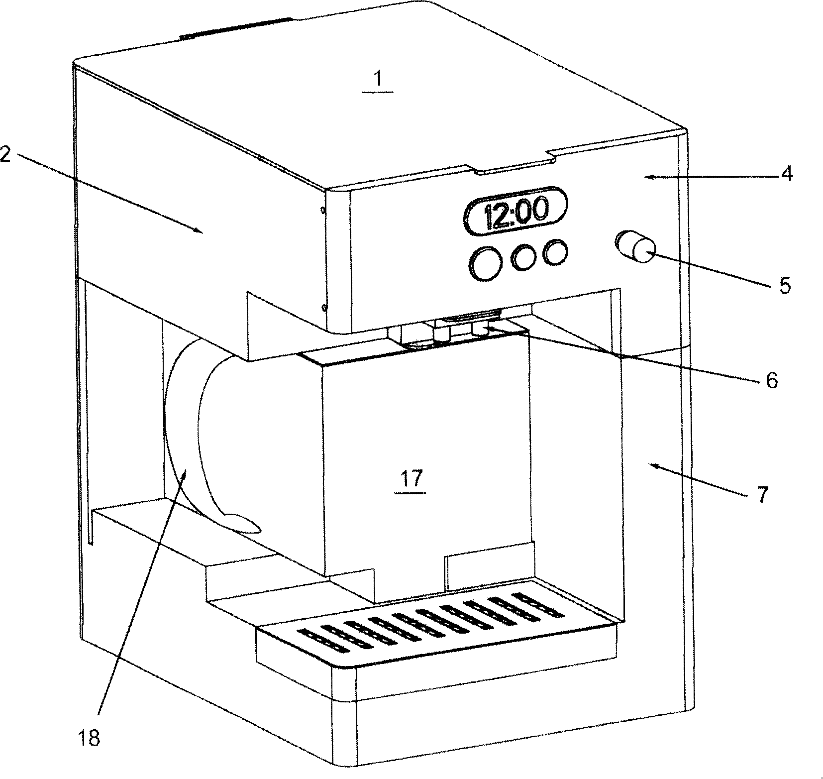
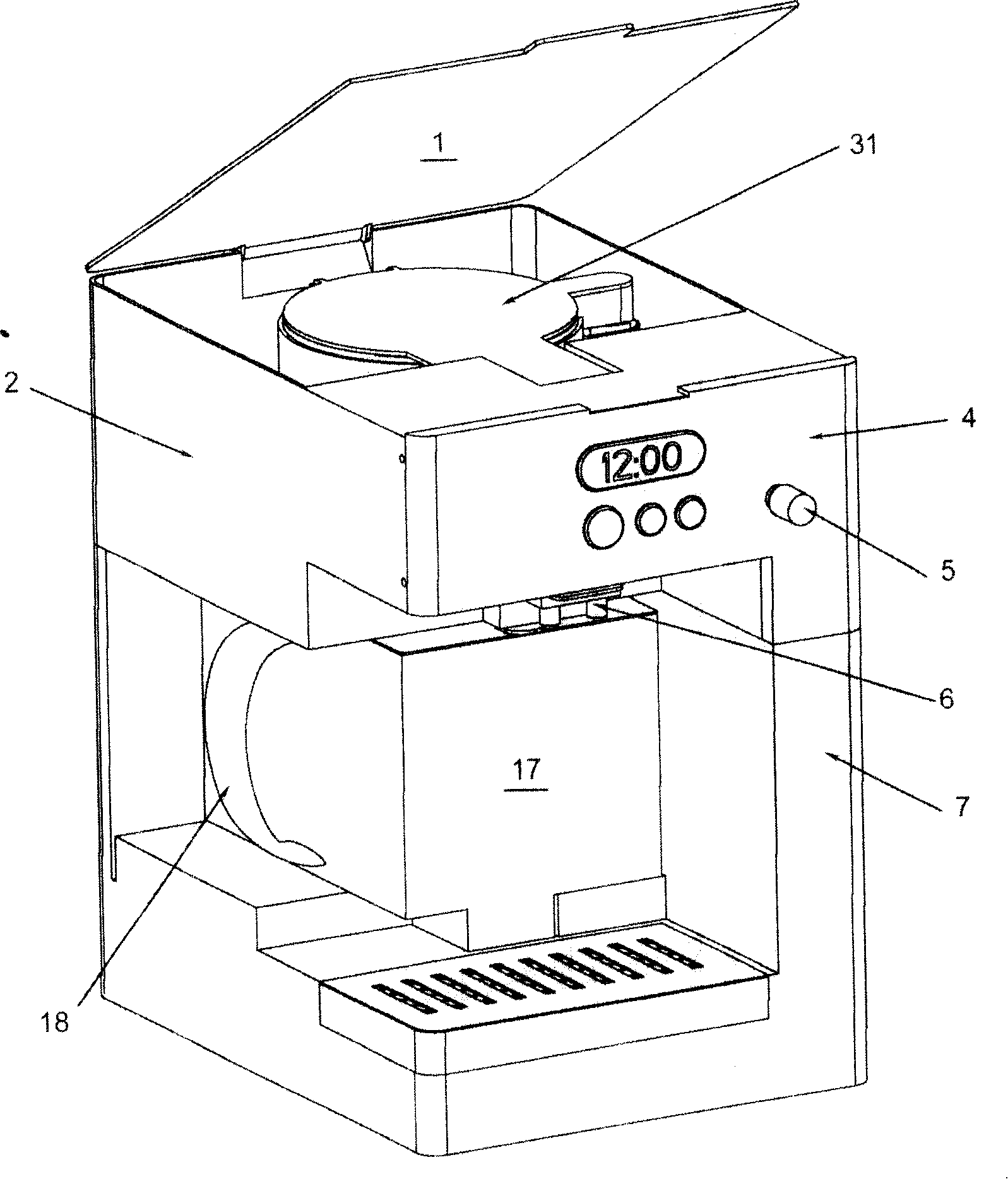
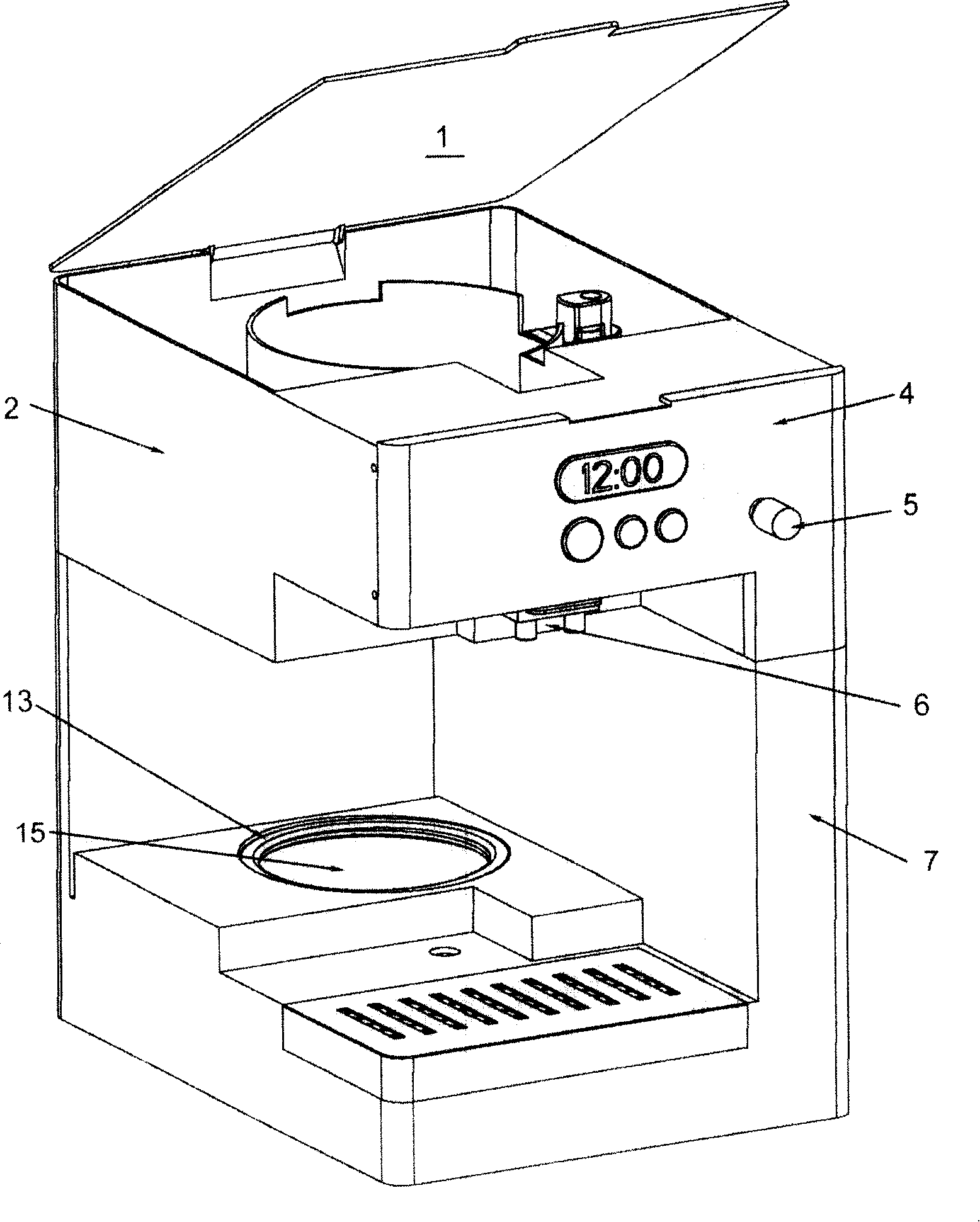
[0025] Embodiment of the hot drink machine with dispensing mechanism of the present invention, as Figure 1 to Figure 7 As shown, it includes: upper cover 1, water tank 2, printed circuit board 3, control panel 4, flow rate adjustment knob 5, nozzle 6, base 7, magnet 8, bracket 9, connecting plate 10, pumping motor 11, heating Tube 12, heat insulating ring 13, leak-proof ring 14, thermal insulation plate 15, distribution pipe 16, beverage tank 17, beverage tank handle 18, magnetic ring 19, gasket 20, pumping propeller 21, mushroom seal 22, connection Card 23, spring 24, beverage box loam cake 25, rod 26, spring 27, seal 28, filter basket 29, beverage output cavity 29a, hot water nozzle 30, nozzle cover 31.

[0026] The base 7 is the support frame of the whole hot drink machine, the water tank 2 is movably installed on the u...


PUM


Abstract

Disclosed is a hot drink maker with a distribution mechanism, comprising a base, a water tank, a filter basket and a heating device. The base is the supporting frame of the hot drink maker; the water tank is actively arranged at the upper end of the base, the filter basket can carry foaming drinks and the heating device is used to boil the water in the water tank; the boiled water can flow from the water tank into the filter basket. The invention also includes a drink tank, a control panel, a circuit board and a pump distribution mechanism; wherein the control panel, the circuit board and the pump distribution mechanism are electrically connected; the filter basket, the drink tank and the pump distribution mechanism are hydraulically connected; the operation of the control panel can enable the circuit board to control the distribution of the ready drink in the drink tank through the pump distribution mechanism; the distributed drink is sent to a drink discharge chamber though a distribution connector. The installation location of the drink tank is free from the height limitations of common cups and travel cups. In the course of drink distribution, a user does not need to hold the cup carefully and can avoid the possibility of being scalded.

Description

technical field [0001] The present invention relates to beverage preparation devices, in particular to components of beverage preparation devices, and in particular to liquid delivery devices in beverage preparation devices. Background technique [0002] Beverage preparation devices in the prior art, especially drip coffee machines, are mostly not provided with a dispensing mechanism. This type of coffee machine uses a carafe and a filter basket, which are easily dirty during use and need to be cleaned after use. After the coffee is brewed, when the carafe is taken out, it is always easy to cause some coffee to drip onto the heating plate, thereby Dirty hot plate and bad smell. In addition, it is also necessary to pour the coffee from the carafe into the cup. If the mouth of the carafe is not well designed, the user will inevitably let the coffee overflow or splash during the operation. [0003] Although newer coffee machines are provided with dispensing operators and larg...

Claims


Application Information

Patent Timeline
Patent Type & Authority Applications(China)
IPC IPC(8): A47J31/02A47J31/46A47J31/54
Inventor 程诒谋
Owner 全能电业科技(深圳)有限公司
Learn More