
Cascade solar cell with amorphous silicon-based solar cell

A technology of solar cells and sunlight, applied in circuits, capacitors, photovoltaic power generation, etc., can solve problems such as the inability to achieve the efficiency and conversion power of multi-junction solar cells

Inactive Publication Date: 2008-06-11
HIGHER WAY ELECTRONICS +1
View PDF0 Cites 13 Cited by
  • Summary
  • Abstract
  • Description
  • Claims
  • Application Information

AI Technical Summary

Problems solved by technology

Although single-junction solar cells are effective, they cannot achieve the performance and conversion power of multi-junction solar cells
Unfortunately, multi-junction and single-junction solar cells are made of different materials and can only capture part of the sunlight and convert it into electricity

Method used


Image

  • Cascade solar cell with amorphous silicon-based solar cell
  • Cascade solar cell with amorphous silicon-based solar cell

Examples


Embodiment Construction

[0018] Before describing the present invention, special terms are defined first, and it should be noted that these special terms are fully applicable to this specification (application).

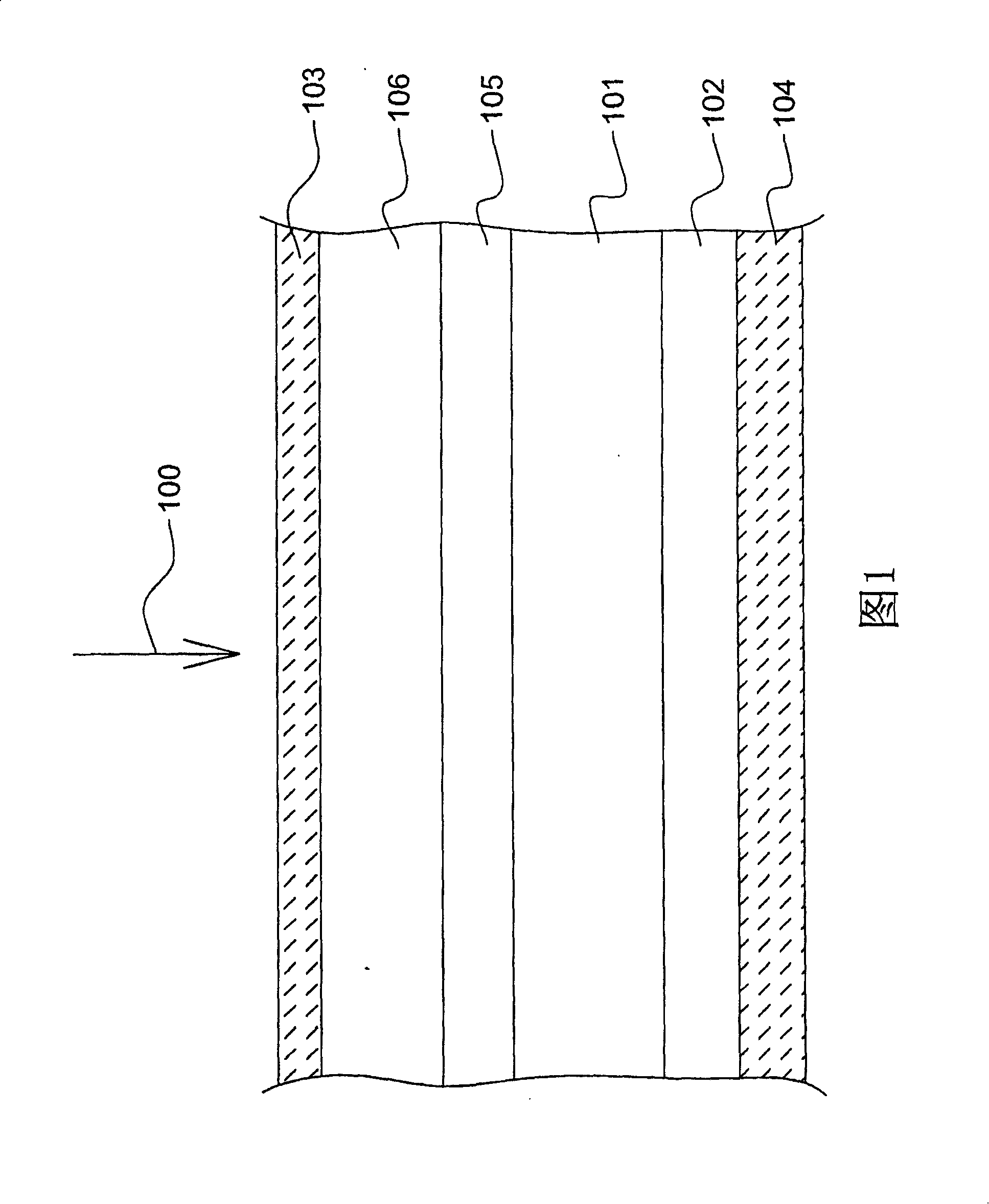
[0019] Please refer to FIG. 1 , according to the spirit of the present invention, a tandem solar cell structure includes a stacked top solar cell disposed on a bottom solar cell. In one embodiment, a p-n single junction type is included in a An active material layer 101 having a single optical bandgap is disposed on a bottom-cell substrate 102 . Optionally, the p-n type and p-i-n type include a multi-layer active material layer 101 with multiple optical bandgaps disposed on the bottom cell substrate 102 . It can be understood that other stacked layers, such as a buffer layer, may be included between the active material layer 101 and the underlying battery substrate 102 , but the present invention is not limited to the above.

[0020] In one embodiment, the bottom battery substrate 102 may b...


PUM


Abstract

A cascade solar cell structure includes an amorphous silicon-based solar cell on a non-silicon solar cell to be configured for an anti-reflective surface and absorbing incident light with short wavelength.

Description

technical field [0001] The invention relates to a tandem solar cell, in particular to a tandem solar cell with an amorphous silicon-based top solar cell. Background technique [0002] In order to maximize the output of photovoltaic electronic components, the number of photons of different energies and wavelengths absorbed by semiconductor materials needs to be continuously increased. The spectrum of sunlight is roughly distributed between 300 and 2200 nanometers, and the corresponding energy is between 4.2 and 0.59 electron volts (eV). In photovoltaic electronic components, the energy difference between the conduction band and the covalent band of semiconductor layers with different doping types that form the absorption layer of the component is called the optical bandgap energy, and the sunlight that can be absorbed by photovoltaic electronic components The energy range depends on this optical energy gap. When the energy of solar radiation is smaller than the optical ener...

Claims


Application Information

Patent Timeline
Patent Type & Authority Applications(China)
IPC IPC(8): H01L31/042H01L31/0376H01L51/42H01L31/078
CPCH01L31/078H01G9/2072Y02E10/50H01L27/302Y02E10/542H01G9/20H01L31/043H01L31/06
Inventor 赖利弘黄堃芳谢文升赖利温
Owner HIGHER WAY ELECTRONICS
Learn More