
Filling structure for fluid exchange column

A technology of fluid exchange and volume, applied in chemical/physical/physical-chemical processes, chemical instruments and methods, chemical/physical processes, etc., can solve the problems of reduced processing efficiency and loss of fluid flow

Inactive Publication Date: 2008-06-04
SNECMA PROPULSION SOLIDE
View PDF1 Cites 2 Cited by
  • Summary
  • Abstract
  • Description
  • Claims
  • Application Information

AI Technical Summary

Problems solved by technology

However, if this increase in exchange area is achieved to the detriment of the flow through the exchange column, for example by using an overly dense packing, the process efficiency will be reduced by reducing the rate at which the fluid flows (renewed), thereby Partially offsets the effect obtained by increasing the exchange area

Method used


Image

  • Filling structure for fluid exchange column
  • Filling structure for fluid exchange column
  • Filling structure for fluid exchange column

Examples


Embodiment Construction

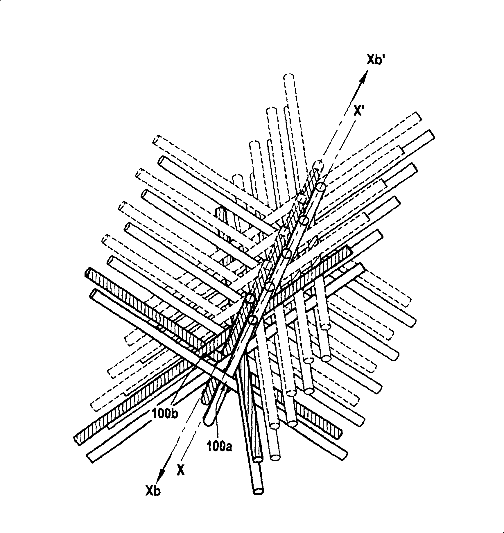
[0028] This description is referenced from Figure 1-4 The described method of manufacturing a filling structure according to an embodiment of the invention begins.

[0029] The structure consists of hollow tube assemblies. Therefore, the first step (step S1 ) is to form a hollow tube. The tube may be made of composite material such as carbon or ceramic (SiC), or indeed of metal, thermoplastic or thermosetting material. The tube preferably has the thinnest possible wall thickness in order to optimize the hollow part of the structure.

[0030] In the case of tubes made of composite materials such as carbon or SiC tubes, the tube can be formed, for example, from braids, filament windings, tapes, or from And tube formation consolidated by liquid techniques, ie by impregnating the braid with a resin such as phenolic resin that can be cokefied and infiltrated and cross-linking the resin by heat treatment.

[0031] The tube is preferably made of carbon / carbon composite material ...


PUM


Abstract

The invention relates to a filling structure used for a fluid exchanging column. The structure restricts an exchanging surface for at least one liquid phase flowing downwards closely contacted with at least one gaseous phase flowing upwards. The structure is characterized in that the invention comprises multi-row containers formed by pipe bundle consisting of pipes (10); each pipe bundle comprises four pipes (10a to 10d) which respectively form the four direction (D10a to D10d) orientations with a certain angle with the axis line of the structure; the pipes form the passage of the external surface leading to the structure (1).

Description

technical field [0001] The present invention relates generally to the field of fluid exchange devices. Such well-known devices generally comprise a cylindrical housing or exchange column in which the exchange of at least two fluids takes place. Typically the exchange is an exchange (substance, heat, etc.) between a downwardly flowing liquid phase and an upwardly flowing gaseous phase. Exchange columns are used, inter alia, to perform operations such as distillation (distillation column), condensation, rectification, adsorption, desorption, separation, extraction, precipitation, chemical reactions, and the like. Background technique [0002] To facilitate the exchange of fluids, it is known to introduce packing elements into the exchange column to increase the contact area between the fluids. Such elements may for example consist of plates, rings (such as Laschig rings), spirals or the like. [0003] It is also known to utilize stacked grids or racks, fibrous packing, and ...

Claims


Application Information

Patent Timeline
Patent Type & Authority Applications(China)
IPC IPC(8): B01J19/32
Inventor 雷米·贝塞特让-皮埃尔·莫米
Owner SNECMA PROPULSION SOLIDE
Learn More