
Plating device

A technology of electroplating device and resistor, applied in the direction of current conduction device, plating tank, electrolysis process, etc., can solve the problems of high cost of rectifier, inability to provide uniform current, and different current values.

Inactive Publication Date: 2008-05-28
辛永议 +3
View PDF0 Cites 3 Cited by
  • Summary
  • Abstract
  • Description
  • Claims
  • Application Information

AI Technical Summary

Problems solved by technology

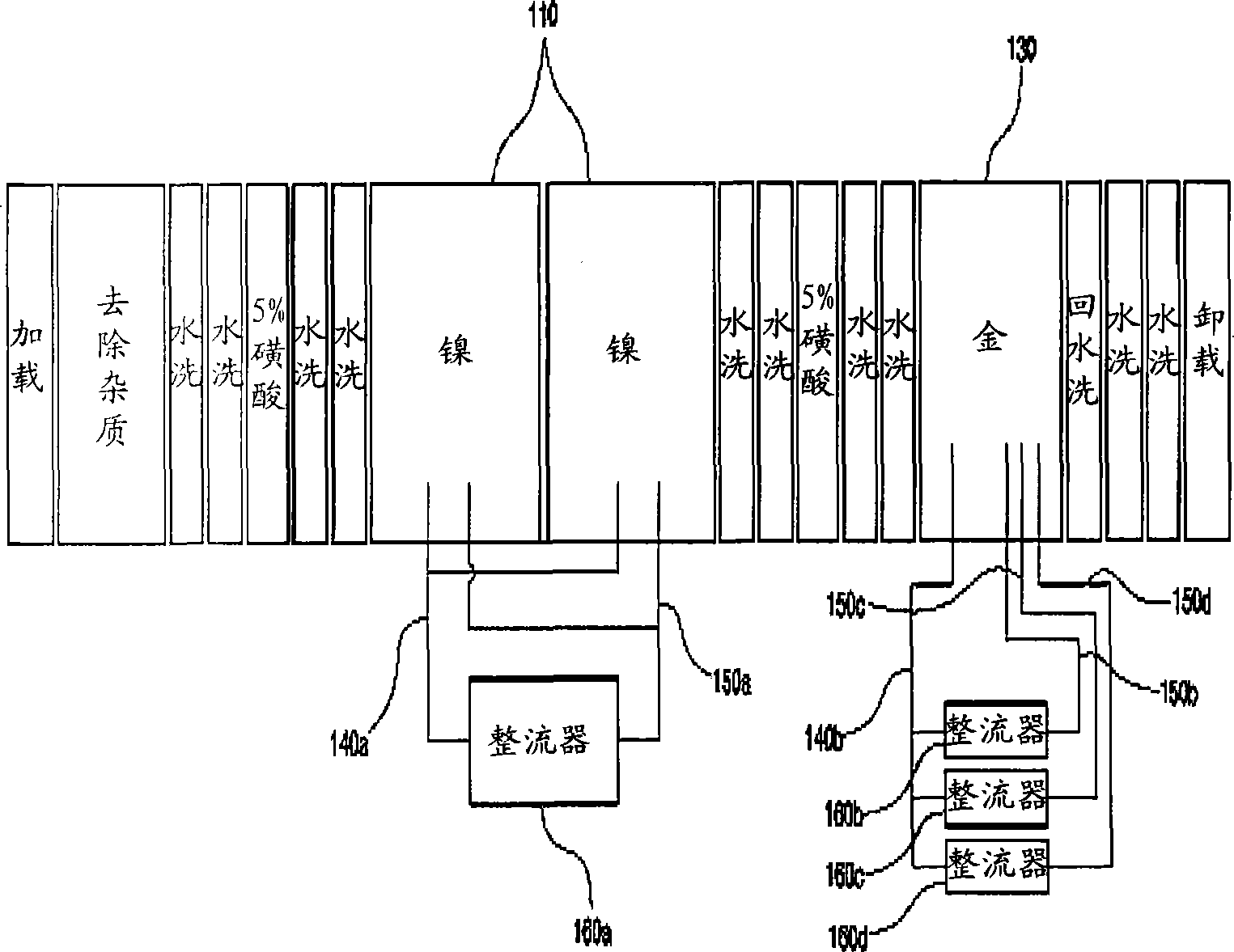
[0008] Here, if gold plating is performed on a complex-shaped object to be electrolyzed, the number of rectifiers (160b, 160c, 160d) needs to be increased in order to connect multiple negative electrodes (150b, 150c, 150d), but the rectifiers (160b, 160c, 160d) The more the number of rectifiers, the higher the cost of the rectifier, resulting in an increase in the cost of the entire gold plating process
[0009] Moreover, in another way of traditional gold / nickel plating, if only one rectifier 160a is used for gold plating, then said one rectifier 160a can only be connected to one negative electrode 150a
[0010] Here, if the shape of the object to be electrolyzed is very complicated, then one negative electrode 150a connected to the one rectifier 160a can only be connected to a part of the object to be electrolyzed with a complex shape, while the object to be electrolyzed that is not connected to the negative electrode 150a The current value of each part of the object is different from each other, so there is a problem that a uniform current cannot be supplied to the object to be electrolyzed

Method used


Image

  • Plating device
  • Plating device
  • Plating device

Examples


no. 1 example

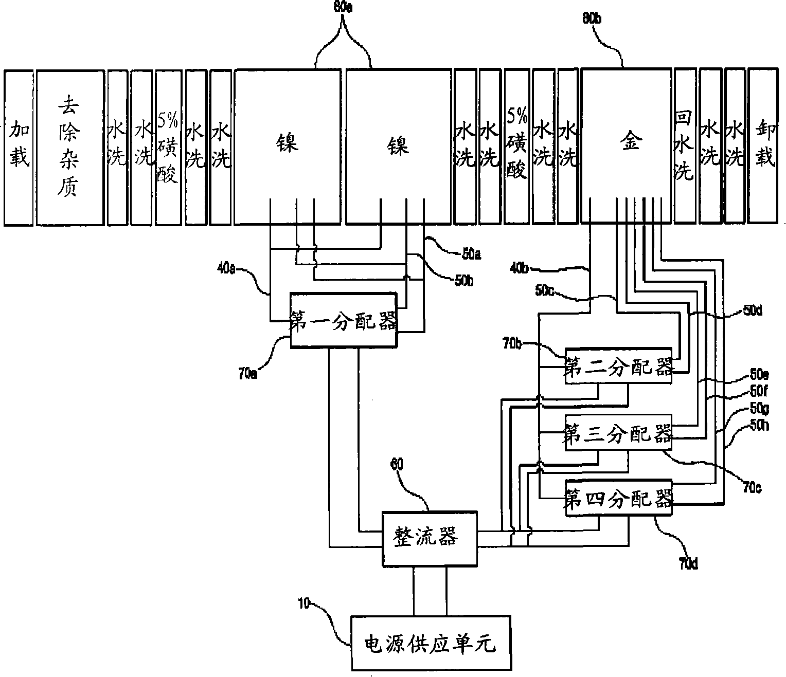
[0079] Below, refer to image 3 The first embodiment of the gold plating process of the electroplating device provided by the present invention as described above will be described.

[0080] First, when gold is plated on the surface of the metal 80 for gold plating, a surface treatment process is performed in order to improve the quality of gold plating. Here, the surface treatment process consists of a process of removing a contamination layer and rust on the surface of the metal for gold plating 80 formed by corrosion, a process of washing with water, and the like.

[0081] Next, nickel plating 80a is performed on the object to be electrolyzed 90 . The first distributor 70a divides the direct current (DC) current provided by the rectifier 60 and supplies it to the first positive electrode 40a and the first and second negative electrodes (50a, 50b). That is, assuming that the direct current (DC) current supplied by the rectifier 60 is 300 amperes, the first distributor 70 a...

no. 2 example

[0091] Below, refer to Figure 4The second embodiment of the gold plating process of the electroplating device provided by the present invention as described above will be described.

[0092] First, when the surface of the gold-plating metal 80 is gold-plated, the surface treatment process for improving the quality of the gold-plating is the same as that of the first embodiment. Here, the surface treatment process goes through a rust removal and water washing process of the surface of the contaminated metal for plating 80 .

[0093] In the next step, nickel plating 80a is implemented on the object to be electrolyzed 90: the first distributor 70a distributes the direct current (DC) current provided by the rectifier 60 and provides it to the first positive electrode 40a and the first and second negative electrodes (50a , 50b). That is, assuming that the direct current (DC) current provided by the rectifier 60 is 30 amperes, the first distributor 70 a supplies a direct current ...

no. 3 example

[0103] Below, refer to Figure 5 The third embodiment of the gold plating process of the electroplating device provided by the present invention as described above will be described.

[0104] First, when the surface of the metal 80 for gold plating is gold-plated, a surface treatment process is implemented in order to improve the quality of the gold plating. Here, the surface treatment process consists of a process of removing the contamination layer and rust formed on the surface of the metal 80 for plating, and a degreasing process of washing with water or removing oil.

[0105] In the next step, the process of nickel plating 80a is implemented on the object to be electrolyzed 90: the first to fourth distributors (70a, 70b, 70c, 70d) distribute the direct current (DC) current provided by the rectifier 60, and provide it to the first to fourth distributors (70a, 70b, 70c, 70d) Fourth positive electrodes (40a, 40b, 40c, 40d) and first to eighth negative electrodes (50a, 50b, ...


PUM


Abstract

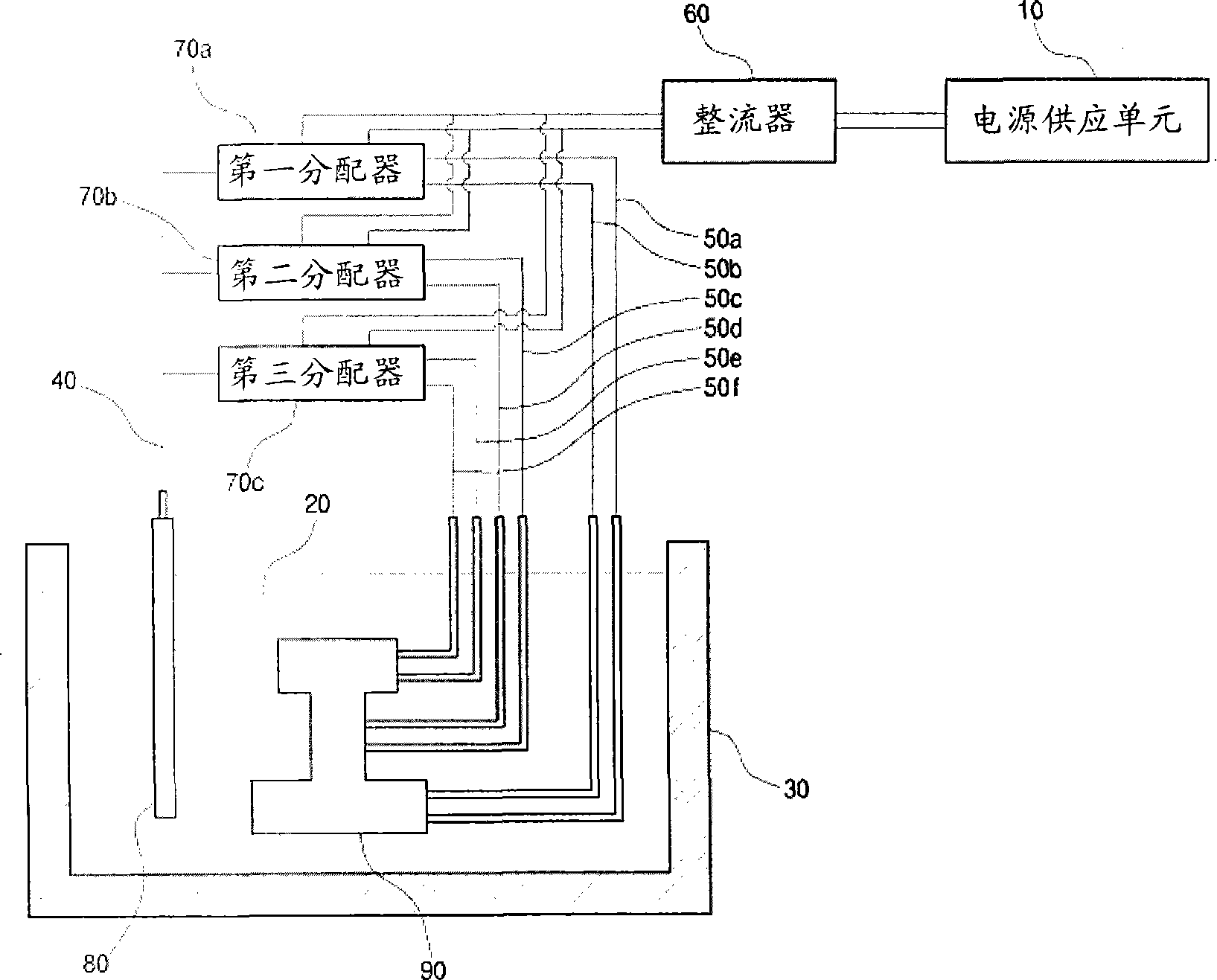
The invention relates to a plating device, comprising a power supply unit, an electrolyte for plating, a plating bath including the electrolyte, a positive electrode connected with a plating metal, a negative electrode connected with an electrolyzed object, a rectifier for converting the AC current supplied by the power supplying unit into DC current, and a distributor connected with the rectifier and used for supplying the DC current converted by the rectifier to the positive electrode and the negative electrode. Therefore, the invention has the advantages that the electrolyzed object can be supplied with even current, thereby ensuring the uniformity of the plating film of the electrolyzed object so as to reduce the rate of poor plating; and a plurality of distributors are adopted to reduce the quantity of the rectifier, thereby reducing the overall expense of the plating process.

Description

technical field [0001] The invention relates to an electroplating device, in particular to an electroplating device which provides uniform current to each position of an object to be electrolyzed through a plurality of negative electrodes connected to a distributor, thereby forming a uniform coating film. Background technique [0002] Generally, gold plating refers to the operation of plating a metal or alloy film on the surface of the electrolyzed object, which is used in various fields such as decorative beautification, corrosion protection, wear resistance improvement, contact resistance improvement, and carbon leaching prevention. [0003] Although this type of gold plating can be divided into various types according to its method and purpose, the so-called gold plating is generally considered to mean electroplating because electroplating is in an important position now. [0004] Here, the principle of electroplating is briefly explained: in electroplating, the gold-plat...

Claims


Application Information

Patent Timeline
IPC IPC(8): C25D17/00C25D19/00
CPCC25D17/007C25D17/04C25D21/12
Inventor 辛永议吉达骏张东奎崔明基
Owner 辛永议
Learn More