
Mold of resin base complex material inner gridding skeletal rod structure and shaping method thereof

A composite material and resin-based technology, which is applied in the field of molds and component forming for inner mesh reinforced structural parts of resin-based composite materials, can solve the problems of poor apparent quality of components, low production efficiency, and low forming accuracy, and achieves the goal of The effect of good quality, improved production efficiency and easy demoulding

Active Publication Date: 2008-05-14
HARBIN FRP INST
View PDF0 Cites 10 Cited by
  • Summary
  • Abstract
  • Description
  • Claims
  • Application Information

AI Technical Summary

Problems solved by technology

[0003] The present invention aims to solve the problems of low molding precision, low production efficiency, high cost, difficult demoulding, relatively complicated process, and poor apparent quality of the formed component in the existing fiber-reinforced resin-based composite material. , providing a mold and component forming method for a resin-based composite inner grid-reinforced structural part. The specific technical solution for solving the above-mentioned problems is as follows:

Method used


Image

  • Mold of resin base complex material inner gridding skeletal rod structure and shaping method thereof

Examples


specific Embodiment approach 1

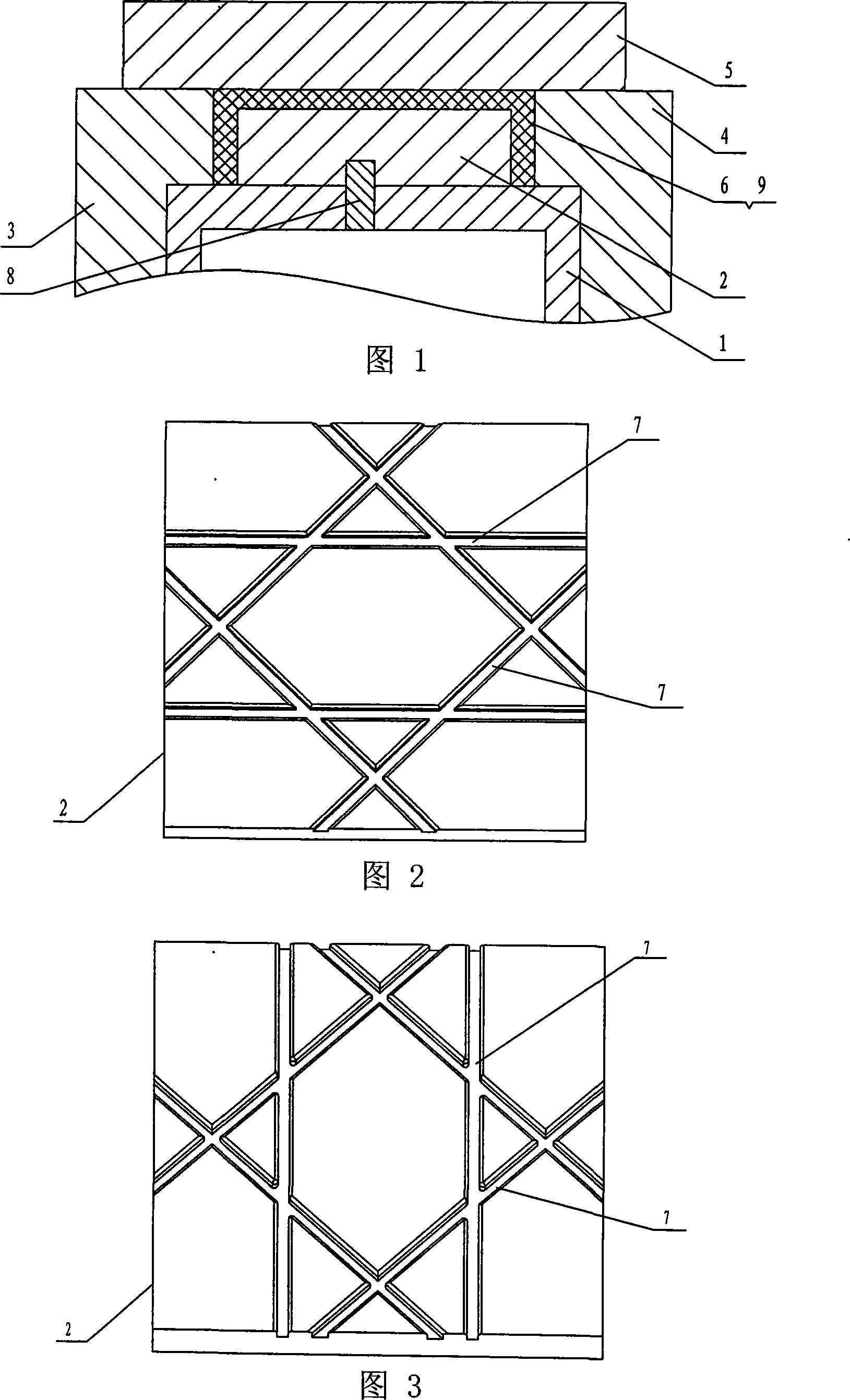
[0013] Specific implementation manner 1: This implementation manner is described in conjunction with FIG. 1 . This embodiment consists of an inner mold 1, a split mold 2, a left flange 3, a right flange 4, an outer mold 5 and a positioning pin 8, and the inner mold 1 is composed of a split mold 2, a left flange 3 and a right Surrounded by side flanges 4, the left flange 3 and the right flange 4 are arranged on both sides of the inner mold 1, and the upper plane of the left flange 3 and the right flange 4 is provided with an outer mold 5, and the inner mold 1. The split mold 2, the left flange 3, the right flange 4 and the outer mold 5 enclose the cavity 6 of the inner grid reinforcement structure of the resin-based composite material, and the upper plane of the split mold 2 is provided with A plurality of grooves 7, the split mold 2 and the inner mold 1 are positioned by positioning pins 8, and the split mold 2 and the inner mold 1 are tightly connected by bolts.

specific Embodiment approach 2

[0014] Embodiment 2: The grooves 7 provided on the split mold 2 in this embodiment are distributed in the longitudinal direction, the transverse direction, the helical direction or a combination thereof.

specific Embodiment approach 3

[0015] Specific embodiment three: the steps of the forming method of this embodiment are as follows:

[0016] Step 1, design the mould, adopt inner mold 1, split mold 2, left flange 3, right flange 4 and outer mold 5, split mold 2 has a plurality of grooves 7 on the upper plane, split The mold 2 and the inner mold 1 are positioned by the positioning pin 8, and the split mold 2 and the inner mold 1 are fastened and connected by bolts;

[0017] Step 2, laying or winding the continuous fiber impregnated with resin base in a plurality of grooves 7 on the split mold 2 of step 1;

[0018] Step 3, laying or winding the continuous fiber impregnated with resin matrix on the outer surface of the split mold 2 in step 1, to fill the cavity 6 of the inner grid reinforcement structure of the resin matrix composite material;

[0019] Step 4: Press the left flange 3 and the right flange 4 respectively on both sides of the cavity 6 of the inner grid-reinforced structure of the resin-based com...


PUM


Abstract

The invention discloses a mold and a component forming method of a resin-based composite material internal grid reinforcement structure, which relates to a mold of a fiber composite material component and a forming method of the component. It solves the problems of low precision, low production efficiency, high cost, poor apparent quality and difficult demoulding in the existing forming method. In the present invention, an inner grid reinforcement member of a resin-based composite material is surrounded by an inner mold (1), a split mold (2), a left flange (3), a right flange (4) and an outer mold (5). The cavity (6), the outer surface of the split mold (2) has a plurality of grooves (7), the split mold (2) and the inner mold (1) are positioned by positioning pins (8), and are connected by bolts and inner molds. Die 1 is firmly connected. The method is as follows: 1. Designing a mould; 2. Winding or laying convex ribs in the cavity; 3. Winding or laying continuous fibers impregnated with resin base in the cavity (6); 4. Forming. The invention has the advantages of high product precision, high production efficiency, reduced production cost, good apparent quality of components, easy demoulding and the like.

Description

technical field [0001] The invention relates to a mold for manufacturing a resin-based composite material internal grid reinforcement structure and a forming method of the component. Background technique [0002] A fiber-reinforced resin-based composite member with an inner grid or a composite member with a structure similar to it, which has excellent performance and is mainly used in aerospace and other fields. This structure is very different from ordinary cylindrical shell members. On the one hand, there are inwardly protruding grid ribs on the inner surface of the cylindrical shell, so it has excellent performance of high load; on the other hand, due to the The protruding grid ribs make the forming process relatively complicated, especially for the design of the forming mold, which puts forward high technical requirements, not only requiring the surface of the mold to have prefabricated grooves, but also to be able to achieve smooth demoulding. At present, the forming m...

Claims


Application Information

Patent Timeline
Patent Type & Authority Applications(China)
IPC IPC(8): B29C33/30B29C33/38B29C70/54B29C70/34
Inventor 林再文陈辉石建军梁岩侯涤详路明坤刘永琪董鹏
Owner HARBIN FRP INST
Learn More