
Coupled shearing force wall energy-dissipation beam-coupled steel plate damper and its using method

A damper and shear wall technology, applied in building components, building structures, earthquake-proof, etc., can solve the problem of not considering the special connection of reinforced concrete coupling beams, the reduction of lateral stiffness and energy dissipation capacity, and the insufficient development of plastic regions, etc. To achieve the effect of enhancing the energy dissipation capacity and collapse resistance of the structure, improving the seismic performance and good energy dissipation effect of the structure

Inactive Publication Date: 2008-05-07
滕军
View PDF0 Cites 41 Cited by
  • Summary
  • Abstract
  • Description
  • Claims
  • Application Information

AI Technical Summary

Problems solved by technology

[0004] However, the dampers shown in attached drawings 21 and 22 are all sheared on the short side of the rectangular profile steel plate. If the profile is changed to make the sheared side longer, its lateral stiffness and energy dissipation capacity will be greatly reduced. , the plastic area developed at the center of the X-shaped steel plate is narrow, the plastic area cannot be fully developed, and failure will occur earlier in the process of greater external force and plastic development
In addition, since the connecting bolt holes are directly arranged on the steel plate, the mild steel will be deformed during the stress process, which will affect the energy dissipation effect
If the damper shown in attached drawing 22 and attached drawing 23 is made with a very long sheared edge, the manufacture and design will be slightly complicated. If there is an in-plane bending moment at both ends of the damper, it is prone to local instability and affects the power consumption. Energy effect
The dampers described in Figure 20, Figure 21, Figure 22 and Figure 23 do not consider the shape of the damper suitable for the structure of the coupling beam, and do not consider the special connection with the reinforced concrete coupling beam

Method used


Image

  • Coupled shearing force wall energy-dissipation beam-coupled steel plate damper and its using method
  • Coupled shearing force wall energy-dissipation beam-coupled steel plate damper and its using method
  • Coupled shearing force wall energy-dissipation beam-coupled steel plate damper and its using method

Examples


Embodiment Construction

[0052] This embodiment is a preferred embodiment of the present invention, and all other principles and basic structures or implementation methods that are the same as or similar to those of this embodiment fall within the protection scope of the present invention.

[0053] The design goal of the connecting beam shear wall structure with the damper attached or replacing the connecting beam in the present invention is: after the damper is replaced or attached to the shear wall connecting beam, the dynamic characteristics of the structure under frequent earthquakes are similar to those of the conventional connecting beam shear wall structure. Unchanging (that is, ensuring that the structural rigidity remains unchanged under normal use). The dampers can fully function under the fortification intensity or rare earthquakes, intensively absorb the structural vibration energy input by the earthquake, and protect the joint shear wall from entering plastic or Limit the plastic development ...


PUM


Abstract

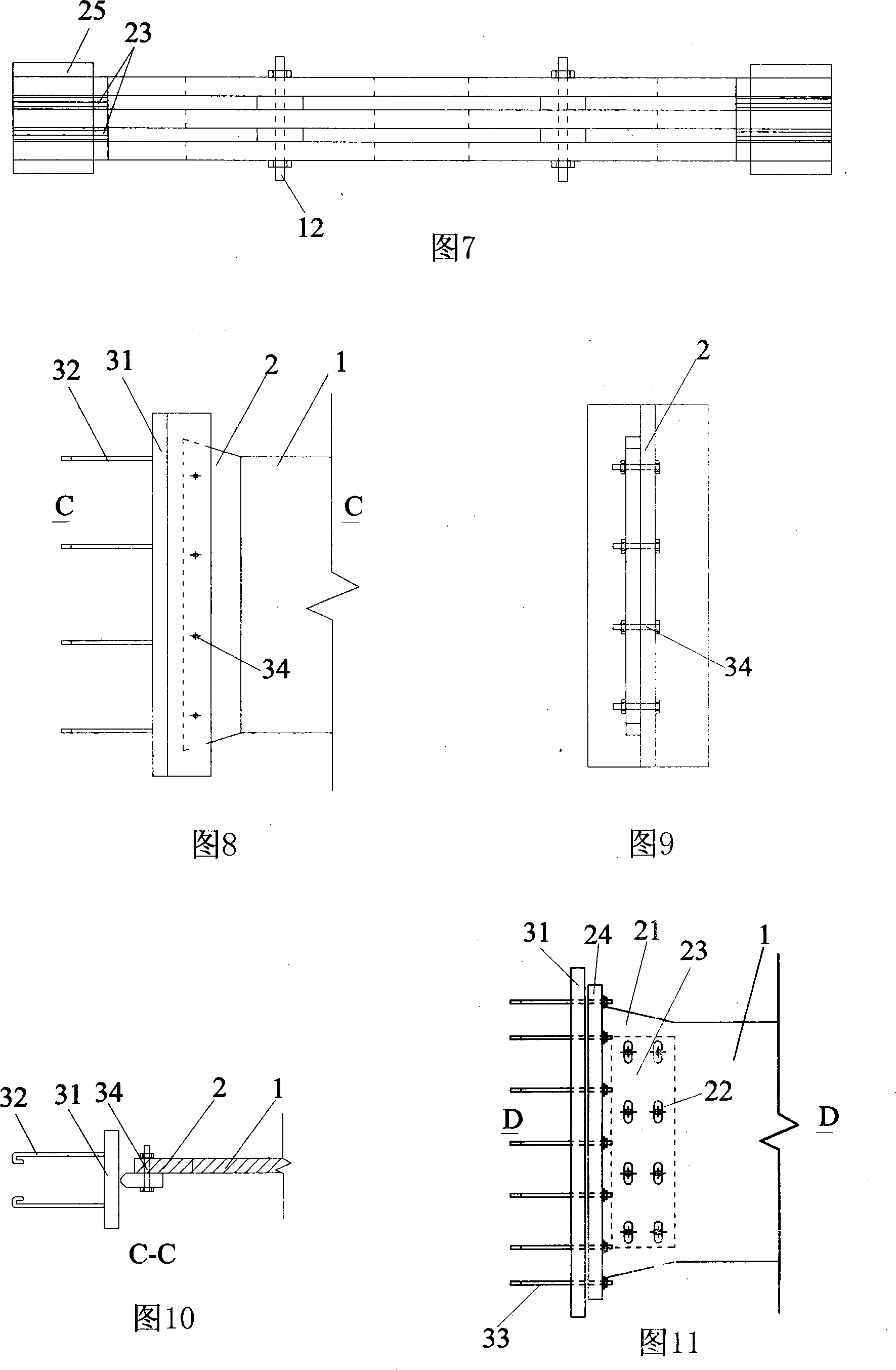
The invention discloses a damper and the application method, in particular to a braced shear wall coupling beam energy dissipating damper and the application method. The damper comprises a mutual connection plastic yield energy dissipating work area and a keeping approximate rigidity partial fixing area, two or more than two column strip-shaped holes are arranged in work area; non-sharp corner processing is adopted at the upper ends of the strip-shaped hole. The application method of the damper for shear wall coupling beam energy dissipating comprises: the reinforced concrete coupling beam is replaced by one or more than one damper; or one or more damper is adhered to the reinforced concrete coupling beam and is positioned at the coupling beam of the shear wall. Each damper work area is provided with anti out-plane instability bolt to prevent the out-plane of each damper from instability; each damper partial fixing area is pre-stretched by high strength bolt, or each damper is welded into a whole body by cap cover plate.

Description

Technical field [0001] The invention discloses a damper and a use method thereof, in particular to a damper for enhancing energy consumption of a connecting beam of a joint shear wall and a use method thereof. Background technique [0002] The joint shear wall structure is a commonly used structural form of high-rise building structures. Its working state and failure mode under the action of an earthquake are closely related to the rigidity and bearing capacity of the connecting beam relative to the shear wall limbs. The structural ductility design requirements follow the principles of "strong limbs and weak beams" and "strong shear and weak bending", but there are often contradictions in ensuring the rigidity and ductility of coupling beams. Therefore, how to satisfy (1) the joint beams and the joint shear wall limbs work together under normal use and frequent earthquakes to provide sufficient lateral stiffness for the joint shear wall structure; (2) in the fortification intensi...

Claims


Application Information

Patent Timeline
IPC IPC(8): E04B1/98E04B1/00
Inventor 滕军马伯涛
Owner 滕军
Learn More