


Quick Research
Generate reliable direction feasibility study reports for your R&D in just a few steps.

Technical Q&A
Discover and master advanced knowledge NOW. Basics, ideas, possibilities, all at once.

Find Solutions
As an expert in R&D theories, this can generate solutions to your technical problems instantly.

Evaluate Feasibility
Analyze your overall solution with one click, know your potential R&D risks in advance.

Monitor Landscape
Get weekly tech updates, stay abreast of the latest tech innovations and key insights.
Roller pressing device
A technology of rollers and pressing force, which is applied to the general parts of printing machinery, printing, rotary printing machines, etc., can solve the problems of increased difficulty, high control overhead, high structural overhead, etc., and achieve the effect of simple modification
- Summary
- Abstract
- Description
- Claims
- Application Information
AI Technical Summary
Problems solved by technology
Method used
Image


Examples
Embodiment Construction
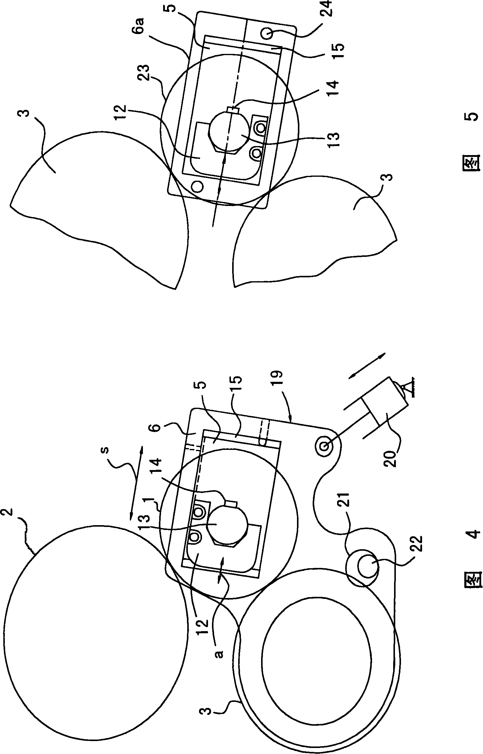
[0022] As mentioned at the outset, the main fields of application of the invention are inking and dampening units of printing presses. These devices consist of rollers which, during operation, are to be pressed against cooperating rollers or cylinders with a specified force. In this case, the roller can be an ink form roller or a so-called intermediate roller. The ink form rollers must additionally be cut off from the associated printing form cylinder.
[0023] The material pairing between the mutually interacting elements is selected such that a soft and a hard surface each cooperate. The contact force brings about a flattening of the softer surface, which should remain as constant as possible during operation. The hard surface is usually the metallic surface of the friction cylinder or the plate cylinder. The ink form rollers and intermediate rollers are covered with rubber to form a soft surface. However, as already mentioned at the outset, the diameter of such rubber c...
PUM
 Abstract
Description
Claims
Application Information
 - R&D Engineer
- R&D Manager
- IP Professional
- Industry Leading Data Capabilities
- Powerful AI technology
- Patent DNA Extraction
Browse by: Latest US Patents, China's latest patents, Technical Efficacy Thesaurus, Application Domain, Technology Topic, Popular Technical Reports.
© 2024 PatSnap. All rights reserved.Legal|Privacy policy|Modern Slavery Act Transparency Statement|Sitemap|About US| Contact US: help@patsnap.com