
Side pump conductive cooling rectangle film laser

A thin-film laser, side-pumped technology, used in the field of lasers

Inactive Publication Date: 2008-04-30
BEIJING INSTITUTE OF TECHNOLOGYGY
View PDF0 Cites 6 Cited by
  • Summary
  • Abstract
  • Description
  • Claims
  • Application Information

AI Technical Summary

Problems solved by technology

Therefore, circular thin-chip solid-state lasers have certain limitations in terms of power upgrades

Method used


Image

  • Side pump conductive cooling rectangle film laser
  • Side pump conductive cooling rectangle film laser
  • Side pump conductive cooling rectangle film laser

Examples


Embodiment Construction

[0017] The present invention will be further described below in conjunction with drawings and embodiments.

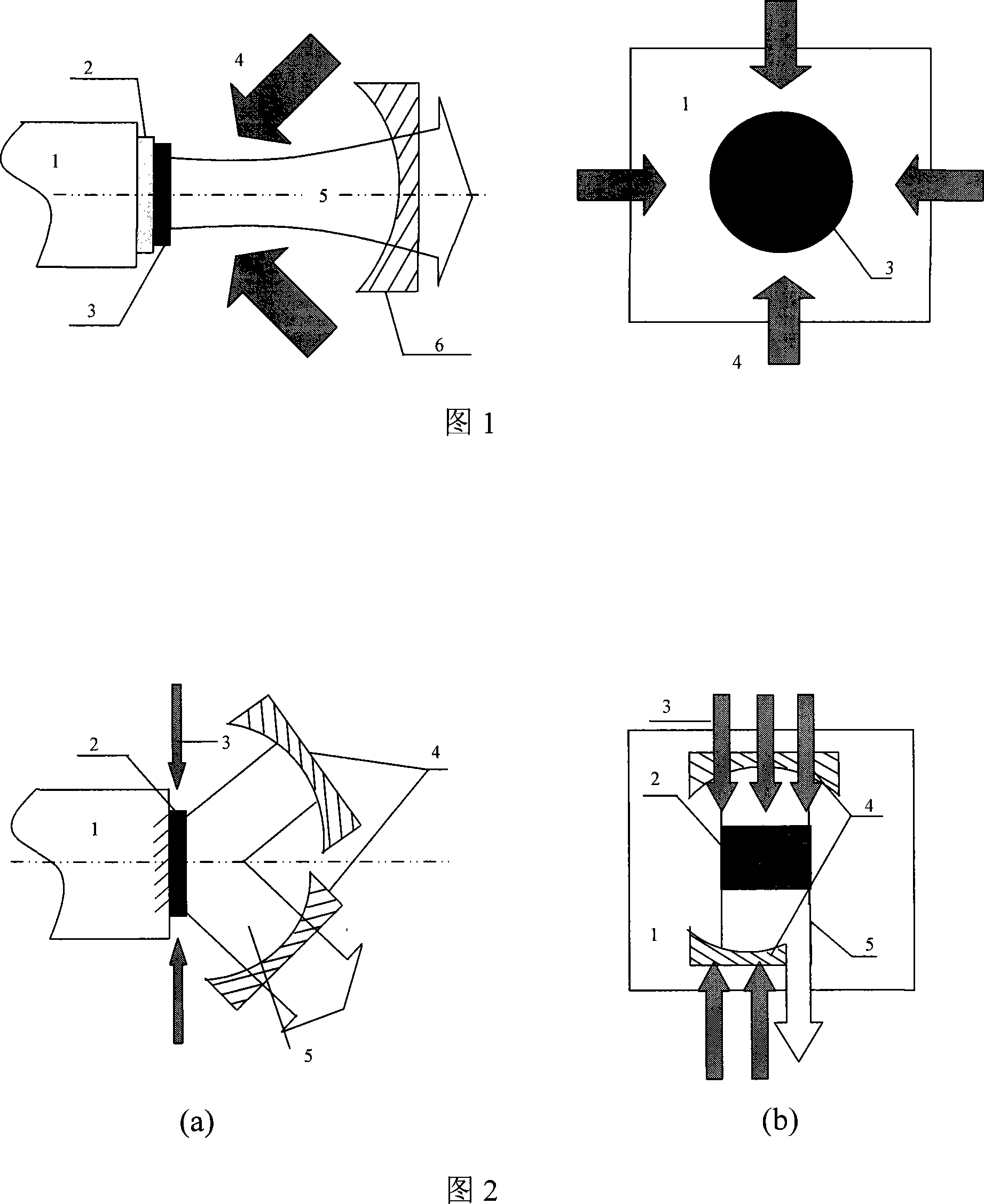
[0018] 1. Using a rectangular sheet gain medium 2 with a size of 0.3mm×5mm×50mm, adjust the cavity mirror 4 to the position shown in FIG. 2 . The side (5mm×50mm) in contact with the heat sink 1 is coated with a high reflection film for oscillating light, and a side-pumped rectangular sheet laser with a mixed cavity as shown in FIG. 2 can be obtained.

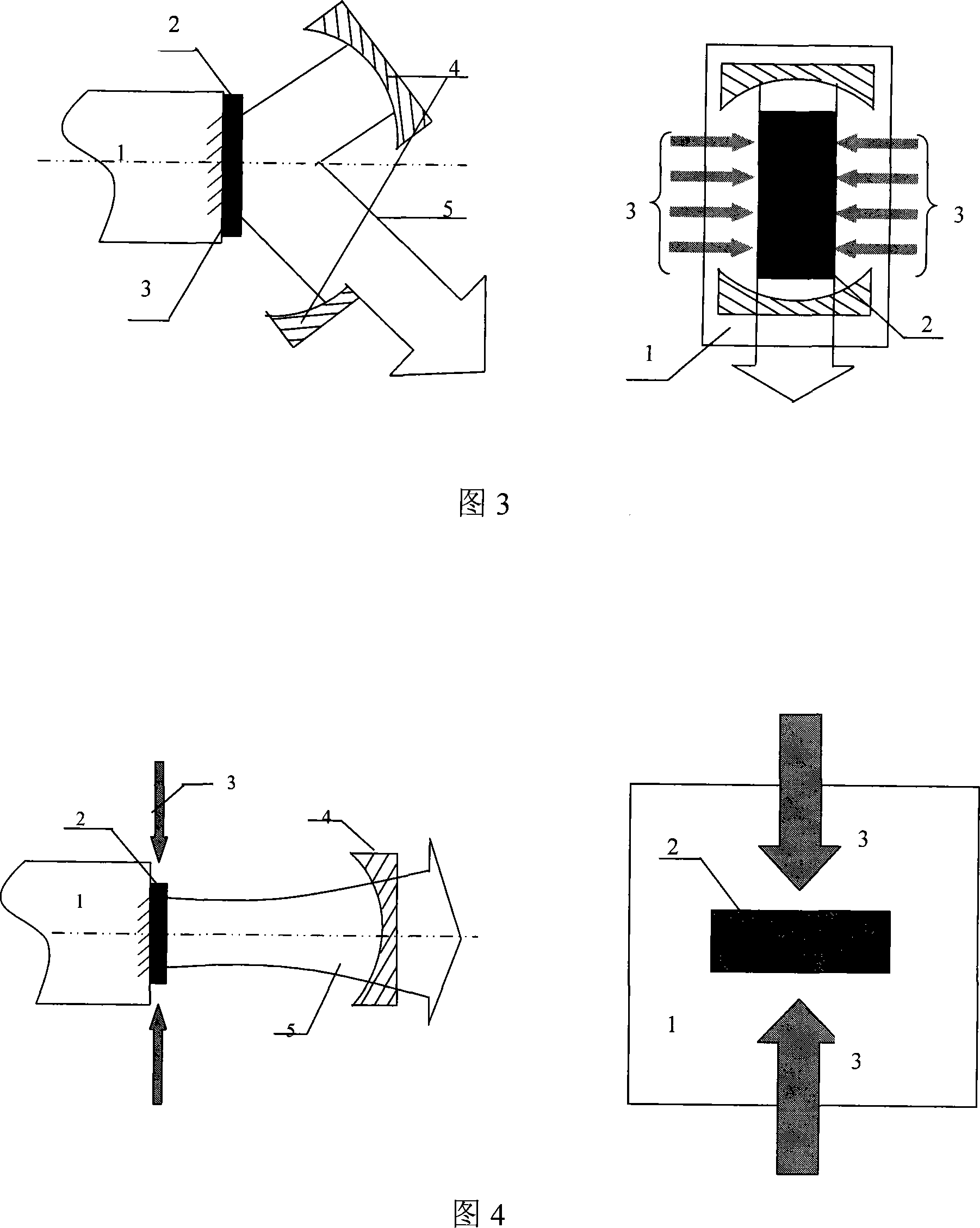
[0019] 2. Using a rectangular sheet gain medium 2 with a size of 0.3mm×5mm×50mm, adjust the cavity mirror 4 to the position shown in FIG. 3 . The side (5mm×50mm) in contact with the heat sink 1 is coated with a high reflection film for oscillating light, and a side-pumped rectangular sheet laser with a mixed cavity as shown in FIG. 3 can be obtained.

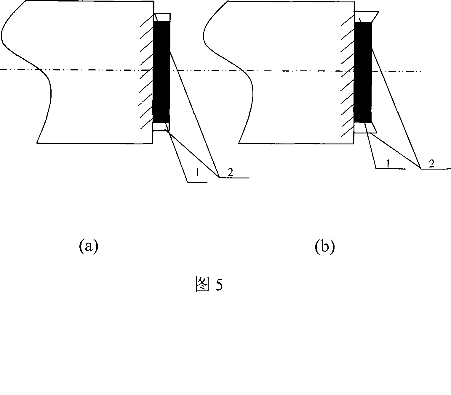
[0020] 3. Combining the rectangular sheet with the stable cavity and adopting the excitation method of side pumping, the schematic diagram of its structure is shown in Fig...


PUM


Abstract

The invention is a rectangular thin-slice all-solid-state laser for lateral surface pump heat conduction and cooling, which belongs to the laser technology field. The laser of the invention takes rectangular thin slices as gain mediums, the gain medium is 0.1-5mm thick, 3-50mm wide, and 5-500mm long. The invention adopts the method of lateral surface pump, utilizes the heat conduction method to conduct cooling, and the resonant cavity thereof can adopt a steady cavity or a steady-non-steady mixed cavity. The invention adopts the rectangular thin-slice gain medium, which can expand the gain medium size to increase the gain volume on the length direction of the gain medium. Meanwhile, the invention adopts a non-steady resonant cavity on the direction, so as to realize the improvement of output power through increasing the length of the gain medium on the premise of not increasing the laser volume and guaranteeing the light beam quality, thereby effectively realizing power upgrade of laser components.

Description

technical field [0001] The invention is an all-solid-state laser that uses a rectangular sheet as a gain medium, adopts a side pumping mode, and uses heat conduction for cooling. It belongs to the field of laser technology. Background technique [0002] Thin-chip all-solid-state laser is an all-solid-state laser device capable of outputting high-power, high-efficiency, high-beam-quality laser beams, and occupies an important position in the field of high-power solid-state lasers. This kind of laser generally uses a laser crystal with a diameter of several millimeters and a thickness of 100-500 microns as the working substance, and fixes it on the heat sink by metal welding or optical glue to achieve a good cooling effect. The pump light is obliquely incident on the working substance, and its structure diagram is shown in Fig. 1 . At present, the continuous output power of a single sheet has exceeded 5KW. At present, the shape of the sheet gain medium selected by the sheet...

Claims


Application Information

Patent Timeline
Patent Type & Authority Applications(China)
IPC IPC(8): H01S3/08H01S3/042H01S3/0941H01S3/16
Inventor 张恒利闫莹王艳华辛建国
Owner BEIJING INSTITUTE OF TECHNOLOGYGY
Learn More