
Electrothermic driven Fabry-perot light modulator

An electrothermal drive and modulator technology, applied in instruments, optics, nonlinear optics, etc., can solve the problems of low display performance of interferometric light modulators, easy pull-in phenomenon in driving, etc., and achieves elimination of pull-in phenomenon and large driving force. , the effect of reducing the requirements of the processing technology

Inactive Publication Date: 2008-04-16
CHONGQING UNIV
View PDF0 Cites 7 Cited by
  • Summary
  • Abstract
  • Description
  • Claims
  • Application Information

AI Technical Summary

Problems solved by technology

[0006] In order to overcome the shortcomings of low display performance of the above-mentioned interferometric light modulator and the phenomenon of pull-in during driving, the present invention proposes a Fappaure light modulator based on electrothermal drive and laser light source illumination, so as to reduce the driving voltage and eliminate the in-drive phenomenon. The pull-in phenomenon improves the contrast ratio of the modulator and the brightness and display characteristics of the projection system

Method used


Image

  • Electrothermic driven Fabry-perot light modulator
  • Electrothermic driven Fabry-perot light modulator
  • Electrothermic driven Fabry-perot light modulator

Examples


Embodiment Construction

[0032] The structure and implementation of the present invention will be described in detail below in conjunction with the accompanying drawings.

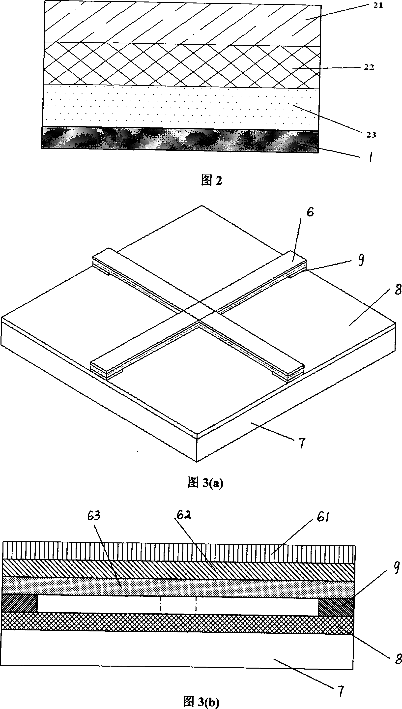
[0033] Figure 1(a) and Figure 1(b) show the structure of a single FAPO optical modulator, 1 is the glass substrate, 2 is the upper reflector, 3 is the FAPO cavity, 4 is the movable lower reflector, 5 is connected to the electric heater The supporting anchors of the drive beam and the lower reflector, 6 is an electrothermal drive component, and 7 is a silicon substrate. The cross-beam-shaped electrothermal driving part 6 is located on the silicon substrate 7, and the electrothermal driving part 6 is provided with a supporting anchor 5 to connect and support the movable lower reflector 4. The transparent glass substrate 1 is suspended and fixed on the silicon substrate 7 by bonding. On the base 7, the upper reflector 2 is attached to the lower surface of the glass substrate 1, and is opposite to the movable lower reflector 4, and the...


PUM


Abstract

An electric heat drive type amber optical modulator for display, the structure at least comprises an electric heat drive part, a movable lower reflector or an upper reflector. The electric heat drive part is a multilayer beam made of two materials with greatly different coefficients of thermal expansion. The initial position between the upper reflector and the lower reflector is K x Lambda / 2 (Lambda represents an incident wavelength and K represents an integer.), and when the reflected light intensity of the incident light is zero after being transmitted by the modulator, the modulator is in a dark state. When an energizing current passes through the electric drive part, the two materials respectively have thermal expansions due to the thermal resistance effect, and a stress which is produced due to the different coefficients enables the electric heat drive part to deform, thereby driving the lower reflector to move upwardly. Accordingly the distance between the two reflectors becomes (2K-1) x lambda / 4, the light intensity after reflection through the modulator reaches a maximal value, and the modulator is in a light state. When the current disappears, the electric heat drive part restores to an original state, the distance between the two reflectors also restores to an original state, and the modulator is in the dark state, too. The modulator realizes the display function based on the principle.

Description

technical field [0001] The present invention relates to an interferometric optical modulator for display; more particularly, the present invention relates to an electrothermally driven Fappaure optical modulator suitable for projection display. technical background [0002] Display is playing more and more important effect in people's daily life, and what occupy main position on the market at present is CRT display and liquid crystal display, and CRT display display color is richer, but bulky. Liquid crystal displays are relatively light in size, but have disadvantages such as slow response speed and low light utilization efficiency. [0003] With the continuous development and maturity of MEMS technology, an optical modulator for display based on optical MEMS technology has been proposed. Representative ones are digital micromirrors (DMDs) and grating light modulators. DMD modulation speed is fast, contrast, brightness and uniformity are very good, but it has the disadvan...

Claims


Application Information

Patent Timeline
Patent Type & Authority Applications(China)
IPC IPC(8): G02F1/21
Inventor 黄尚廉孙吉勇张洁张智海史玲娜
Owner CHONGQING UNIV
Learn More