Trace heating for oil well viscosity,coagulation reduction and dewaxing

A technology of heat tracing and viscosity reduction, which is used in cleaning appliances, wellbore/well components, isolation devices, etc., can solve the problems of reducing the space for economic benefits, increasing the cost of crude oil production, and yet to see a successful solution. Achieve the effect of improved technical level, low construction cost and easy implementation

Inactive Publication Date: 2008-04-16
姜永民
View PDF0 Cites 5 Cited by
  • Summary
  • Abstract
  • Description
  • Claims
  • Application Information

AI Technical Summary

Problems solved by technology

Although the above methods have been used for many years and have played a positive role in the exploitation of high pour point oil and high waxy oil, they all have the problem of high cost. For example, each well costs 80,000 to 200,000 more per year than ordinary oil production wells. In particular, the fourth method is only suitable for group wells, and only one gas-fired dual-purpose furnace costs 3.5 million yuan; some have a short service life, such as pinching an electric heating cable for 80,000 yuan, which increases the cost. Reduce the cost of crude oil extraction, so that oil production companies operate at high costs, and the space for economic benefits is significantly smaller
Therefore, oil production companies and related scientific research units have invested scientific and technological elites and funds in an attempt to develop low-cost and effective processing methods and devices suitable for mining high-condensing, viscous, and high-waxy oils as soon as possible. So far, no reports of successful solutions have been seen, which has led oil production companies to continue to use traditional methods year after year helplessly.

Method used


Image

  • Trace heating for oil well viscosity,coagulation reduction and dewaxing
  • Trace heating for oil well viscosity,coagulation reduction and dewaxing
  • Trace heating for oil well viscosity,coagulation reduction and dewaxing

Examples


Embodiment Construction

[0018] The present invention is described in detail by means of embodiments in conjunction with the accompanying drawings.

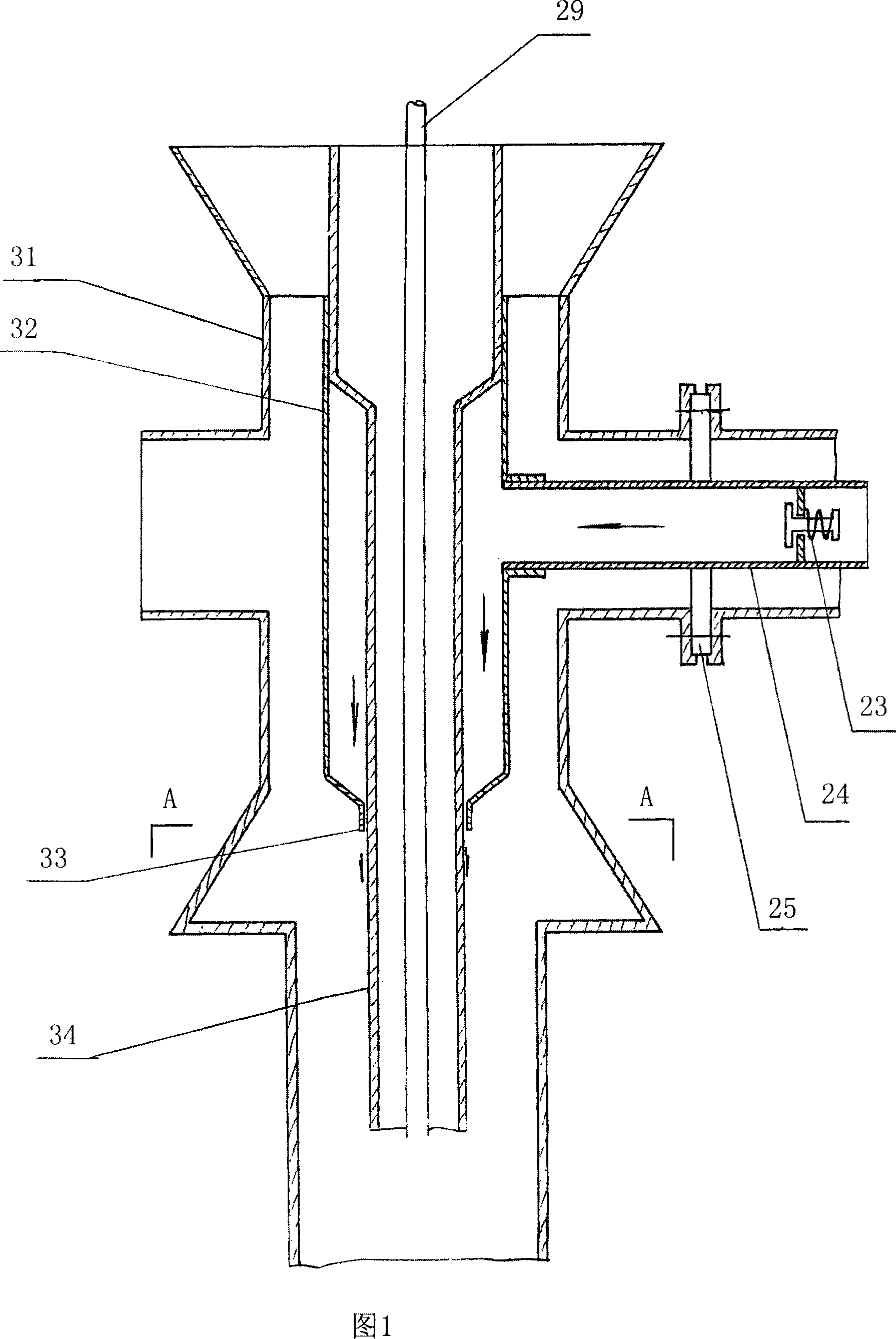
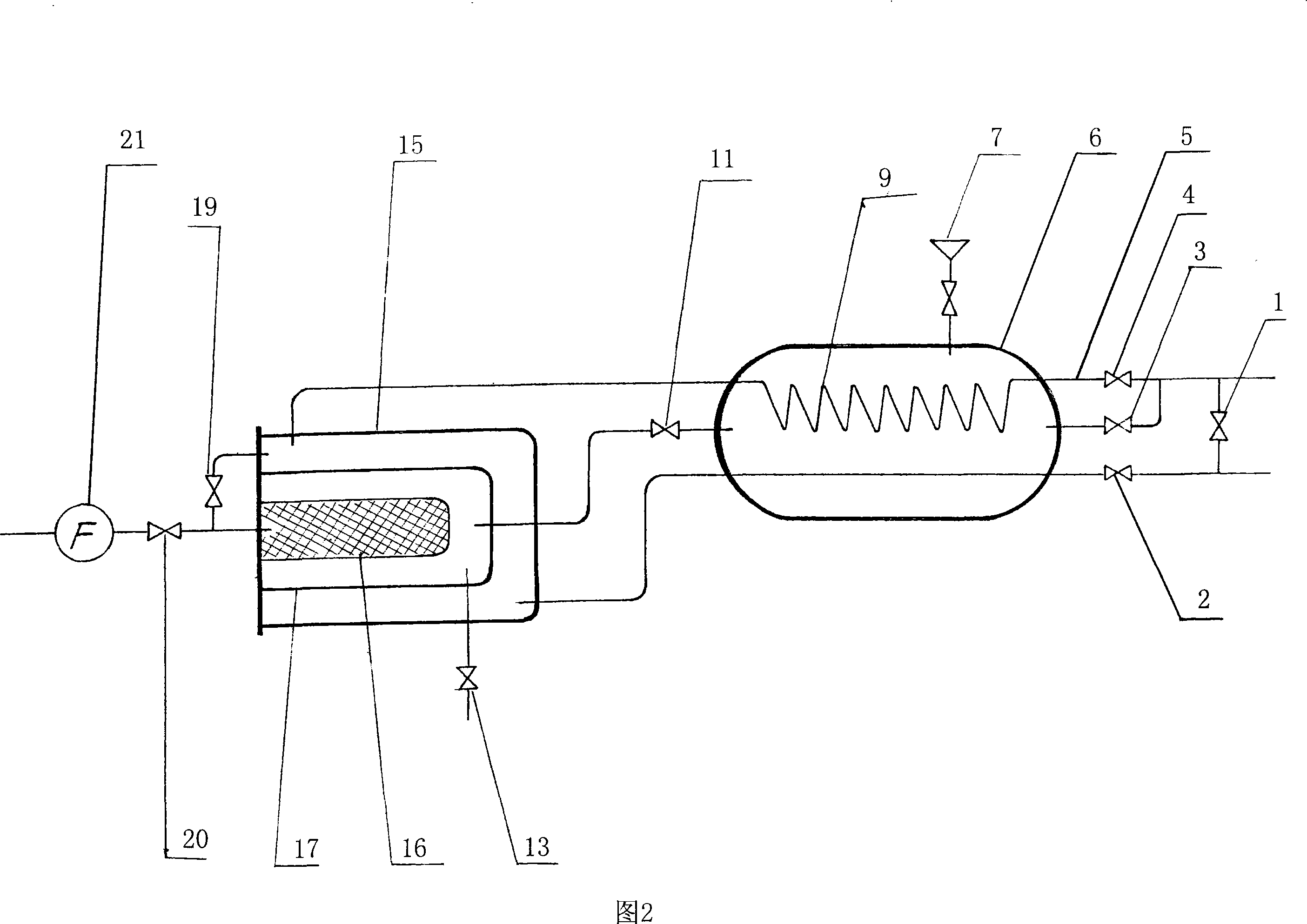
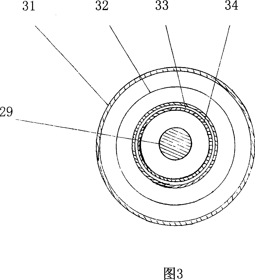
[0019] As shown in Figure 1, the lower end of the buffer 32 penetrates into the main cavity of the large cross 31 and is installed on the upper part of the oil pipe 34, the upper inner wall of the buffer 32 is tightly combined with the upper outer wall of the oil pipe 34 to prevent water from crossing, and the lower end of the water outlet 33 There is a gap between the oil pipe 34 and the outer diameter of the oil pipe 34, and one side is provided with a pipe interface connected to one end of the hot water inlet pipe 24, and the other end of the hot water inlet pipe 24 is provided with a check valve 23, and passes through the flowmeter 21 , the flow control valve 20, the filter 16, the water supply valve 11, the water tank 6 and the water supply valve 3 are connected to the pipeline of the hot water circulation system of the well station, as shown in Figu...


PUM


Abstract

The invention relates to an oil pumping subordinate device, in particular to a heater for reducing stickiness and concretion, and dewaxing of an oil well, which is a preferred heater for the pumping of an oil well with high-concreted oil, high wax content and heavy oil. The invention consists of a sucker rod, a large cross joint, an oil pipe and a sleeve. A buffer passes into a main cavity of the large cross joint and is arranged on the periphery of the upper part of the oil pipe; the upper end of the buffer is tightly combined with the outer wall of the corresponding part of the oil pipe; an outflow clearance is arranged between the inner wall of an outlet of the lower end of the buffer and the outer wall of the oil pipe; one side of the buffer is provided with an interface connected with an inlet branch of hot water; the inlet end of the inlet branch of hot water is connected with a hot water circular pipeline of a well station. In the invention, a line is connected with the prior hot-water circular system of the well station, above 95 DEG C hot water is extracted, 2-3 m<3> hot water is consumed every 24 hours, the effects of dewaxing and concretion reduction are good, the effects are better if little pour point depressant is added; the extraction cost of thick oil with high wax content is decreased; the thermal source in the prior hot-water circular system of the well station is adopted; a water-can inner fuel can also be used for heating or supplementary heating. The invention is of easy implement and low cost.

Description

technical field [0001] The invention relates to an auxiliary facility for oil production, in particular to a heat tracer for oil well viscosity reduction, condensation and wax removal, which is the preferred heat tracer for oil wells with high pour point oil, high wax content and viscous oil wells. Background technique [0002] According to statistics, there are waxy oil wells in all major oil wells in the country. In particular, the Shenyang Oil Production Plant of Liaohe Oilfield is a world-class high pour point oil production base, with a solidification point of 72°C, especially in the pipe section 700-800 meters away from the wellhead. Seriously, often the accidents of stuck oil pump or sucker rod damage occur from time to time, which makes the exploitation of this type of crude oil increase many technical difficulties and production costs. In the past, in order to solve the above problems, the following four methods are usually adopted: 1. Put an 800-meter-long electric...

Claims


Application Information

Patent Timeline
Patent Type & Authority Applications(China)
IPC IPC(8): E21B36/00E21B37/00E21B43/24
Inventor 姜永民
Owner 姜永民
Why Eureka
Try Eureka