
CAN bus network and CAN bus extension method

A CAN bus and bus network technology, applied in the field of CAN bus network, can solve problems such as rising costs and achieve the effect of reducing costs

Inactive Publication Date: 2008-04-09
EASTCOMPEACE TECH
View PDF0 Cites 7 Cited by
  • Summary
  • Abstract
  • Description
  • Claims
  • Application Information

AI Technical Summary

Problems solved by technology

But this requires independent development and operation of each CAN bus, and the need to purchase independent control equipment, resulting in a sharp rise in costs

Method used


Image

  • CAN bus network and CAN bus extension method
  • CAN bus network and CAN bus extension method
  • CAN bus network and CAN bus extension method

Examples


no. 1 example

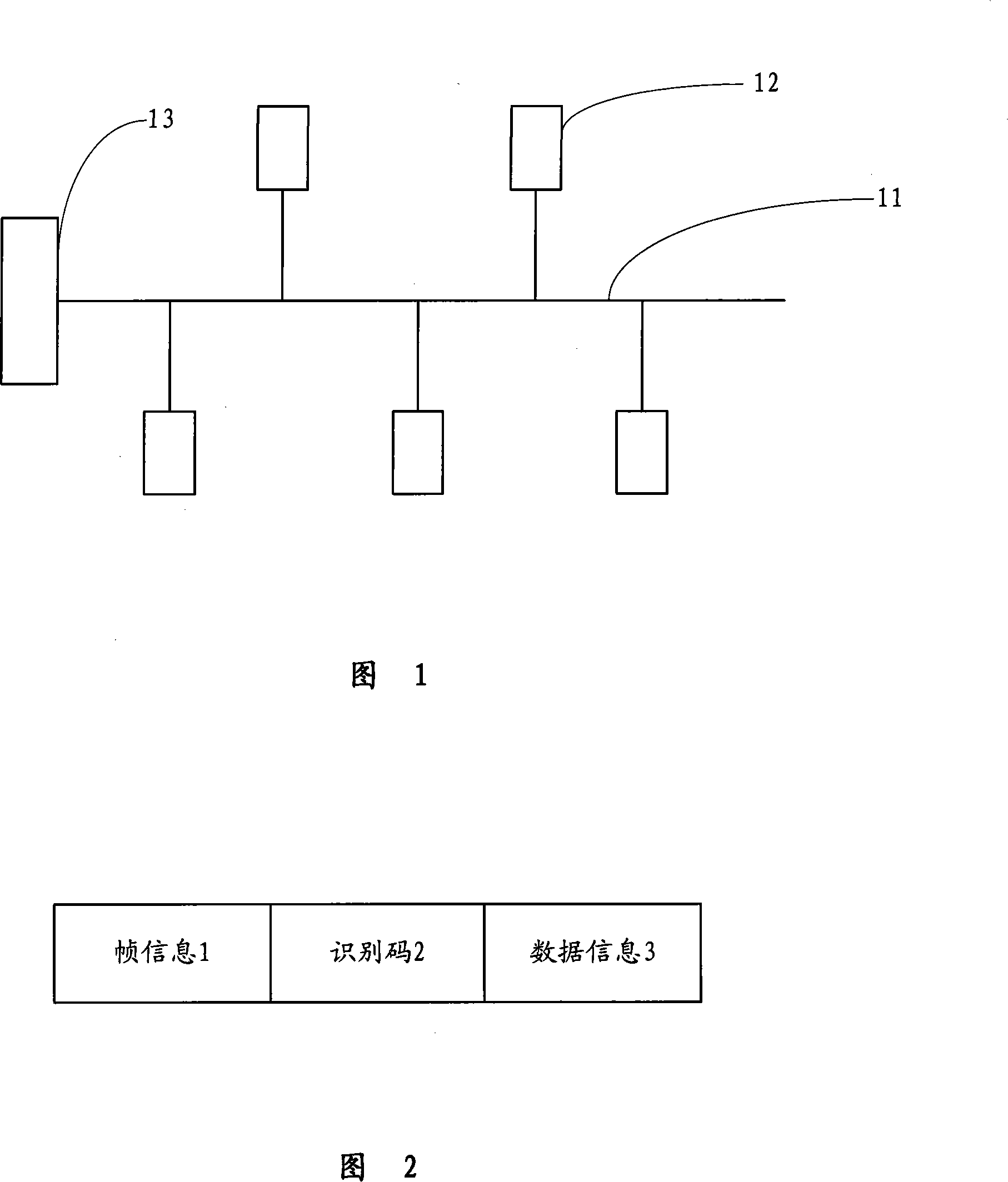
[0027] Referring to FIG. 3, FIG. 3 is a schematic diagram of the connection structure of the first embodiment of the present invention. It can be seen from the figure that there are four bus controllers 13 in this embodiment, and each bus controller 13 is connected with four bus channels 11, and each bus channel 11 is connected with a plurality of equipment terminals 12. The connection between the terminal equipment 12 and the bus channel 11 and the connection between the bus channel 11 and the bus controller 13 are the same as those of the existing CAN bus, and will not be repeated here.

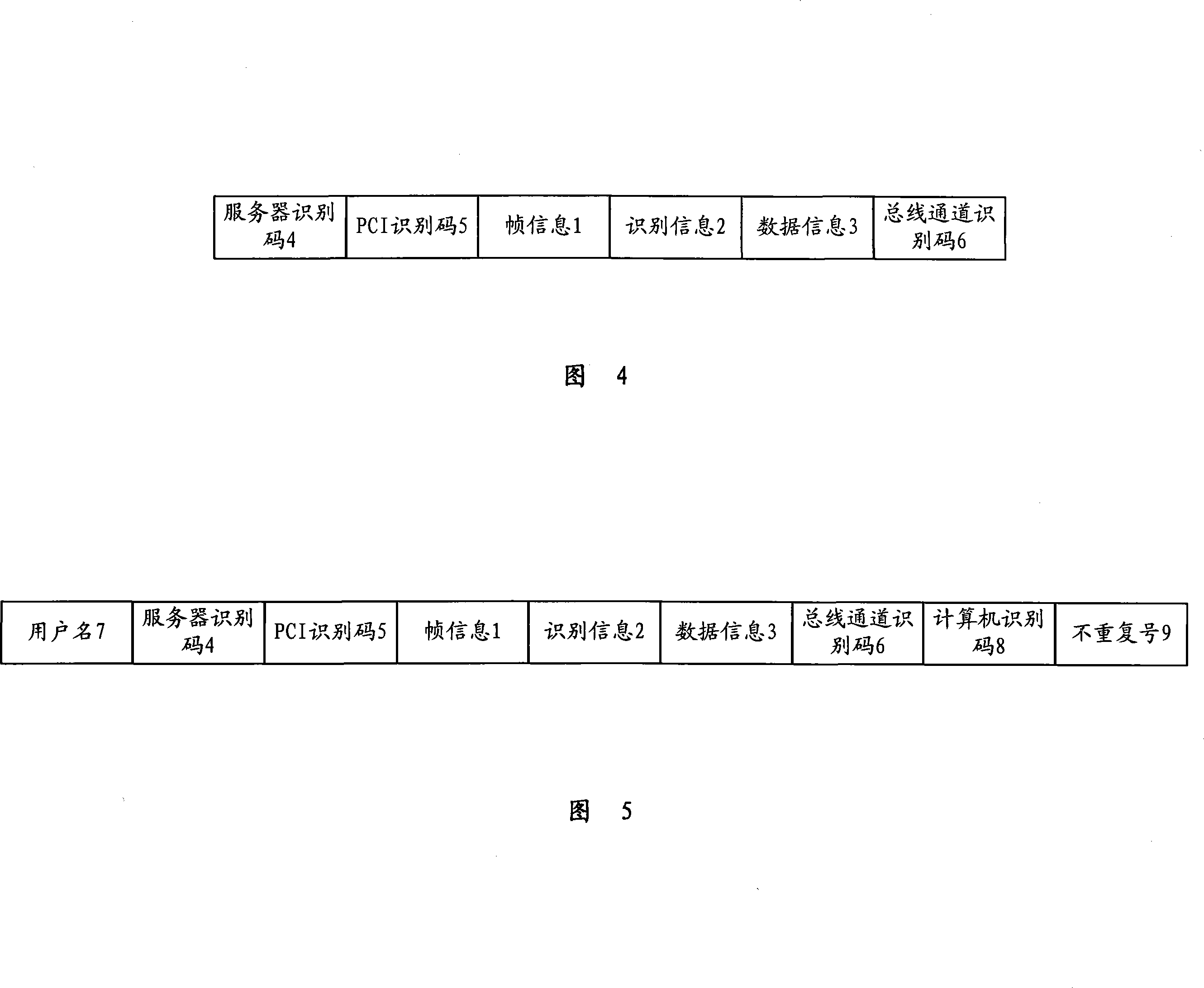
[0028] In this embodiment, each bus controller 13 is connected to the server 15 through a PCI slot 14, wherein the PCI slot 14 is a connection slot in this embodiment. Each server 15 is provided with a first-level expander. The first-level expander is a data processing device arranged in the server, which can process the communication frame transmitted therein, that is, add corresponding id...

no. 2 example

[0041] However, in today's industrial production, it is often not enough to use only one computer to control all terminal equipment, and usually requires multiple computers to operate at the same time, which requires a second expansion of the CAN bus network to enable CAN The bus network can be operated simultaneously by several computers.

[0042] Referring to FIG. 6, FIG. 6 is a schematic diagram of the connection structure of the second embodiment of the present invention. Compared with the first embodiment, the CAN bus network of the present embodiment also includes two servers 15, each server 15 is connected with the bus controller 13 through the PCI slot 14, and each bus controller 13 is connected with multiple A bus channel 11, on which less than 120 terminal devices 12 are connected. In this embodiment, each server 15 is provided with a second-level expander in addition to a first-level expander, and the second-level expander and the first-level expander in the same s...


PUM


Abstract

The invention provides a controller area network (CAN) bus network and a CAN bus extension method. The CAN bus network comprises but controllers, a group of terminal equipments connected through a but channel, a server connected with a plurality but controllers, and a equipment management terminal connected with a plurality of servers, wherein the server is provided with a first-level extender. The CAN but extension method comprises that the equipment management terminal sends a downlink communication frame containing a first-type identification code to a specific terminal equipment, and when the downlink communication frame is sent to the first-level extender, the first-level extender deletes the first-type identification code in the downlink communication frame; and the terminal equipment sends an uplink communication frame to the equipment management terminal, and when the uplink communication frame is sent to the first-level extender, the first-level extender adds the first-type identification code in the uplink communication frame. The invention can connect a large number of terminal equipments on the CAN but network, and assure that the terminal equipments can both accurately communicate with the equipment management terminal.

Description

technical field [0001] The invention relates to a CAN bus network, in particular to a CAN bus network and a CAN bus expansion method applied in the fields of automobile control, industrial production and the like. Background technique [0002] With the development of industry, various field buses are increasingly used in industrial production to control the terminals of production equipment in order to realize the automation of production. At present, the common field buses in industrial production include RS-232-C bus, RS-485 bus, I 2 C bus and CAN (Controller Area Network) bus, etc., and CAN bus has the advantages of strong anti-interference and reliable use, and is more and more popular. [0003] Referring to Fig. 1, Fig. 1 is a schematic diagram of the connection structure of the existing CAN bus. The existing CAN bus includes a bus controller 13 connected to a bus channel 11 . The bus channel 11 can be made of twisted pair, coaxial cable or optical fiber for transmit...

Claims


Application Information

Patent Timeline
Patent Type & Authority Applications(China)
IPC IPC(8): H04L12/28G05B19/418
CPCY02P90/02
Inventor 周杰王国庆
Owner EASTCOMPEACE TECH
Learn More