
Portable vehicle mounted dualpurpose wrench

A dual-purpose, hand-sleeve technology, applied in the direction of wrench, metal processing, wrench, etc., can solve the problems of high failure rate, tightening nut tightness, inability to accurately control torque, inconvenient upper and lower lines, etc., to achieve light and fast handling. Hands on and off rail lines, light weight, compact effect

Active Publication Date: 2010-04-07
CANDQ AMUSEMENT EQUIP CO LTD
View PDF5 Cites 0 Cited by
  • Summary
  • Abstract
  • Description
  • Claims
  • Application Information

AI Technical Summary

Problems solved by technology

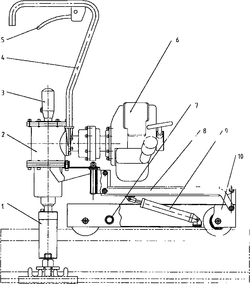
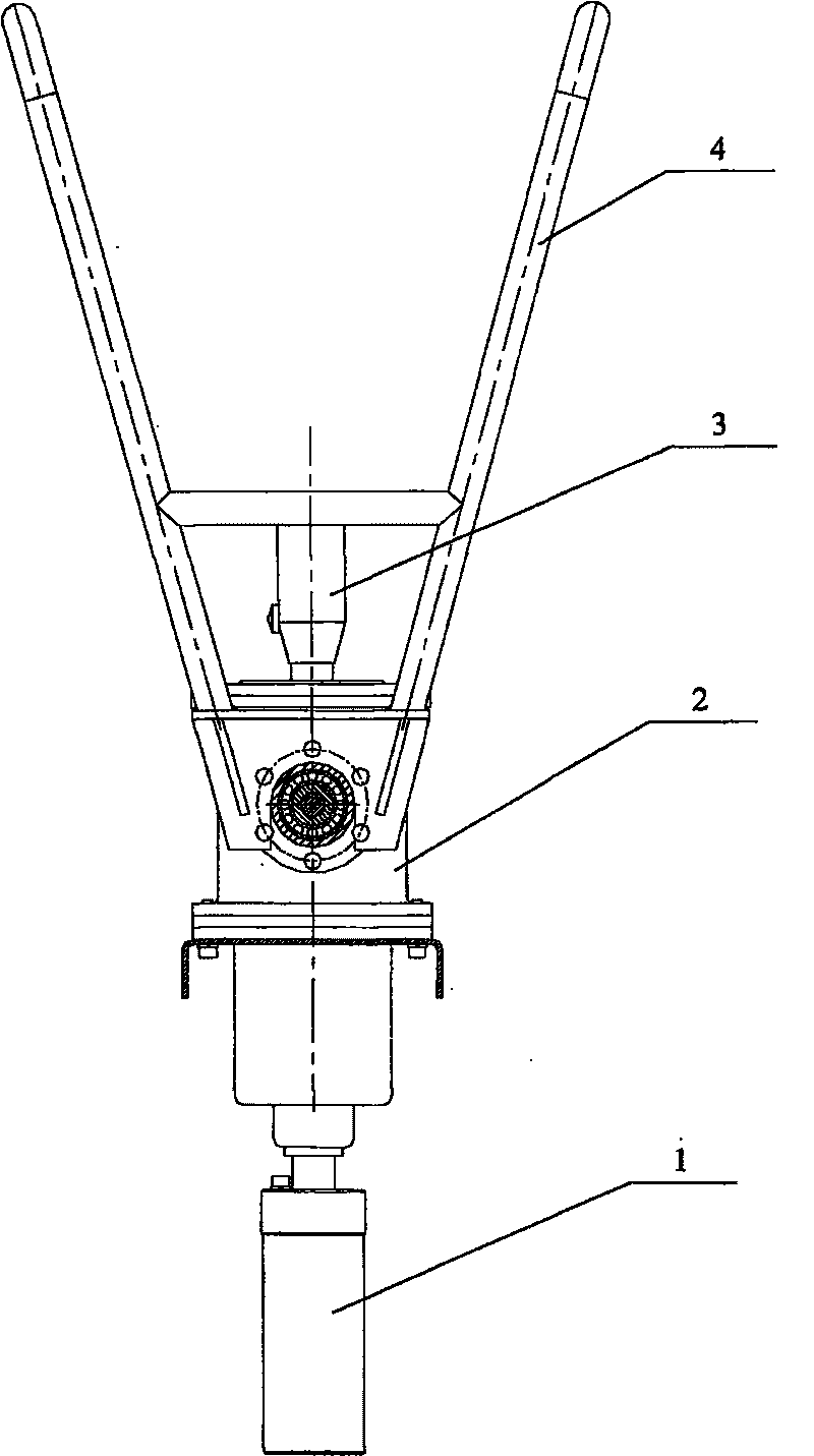
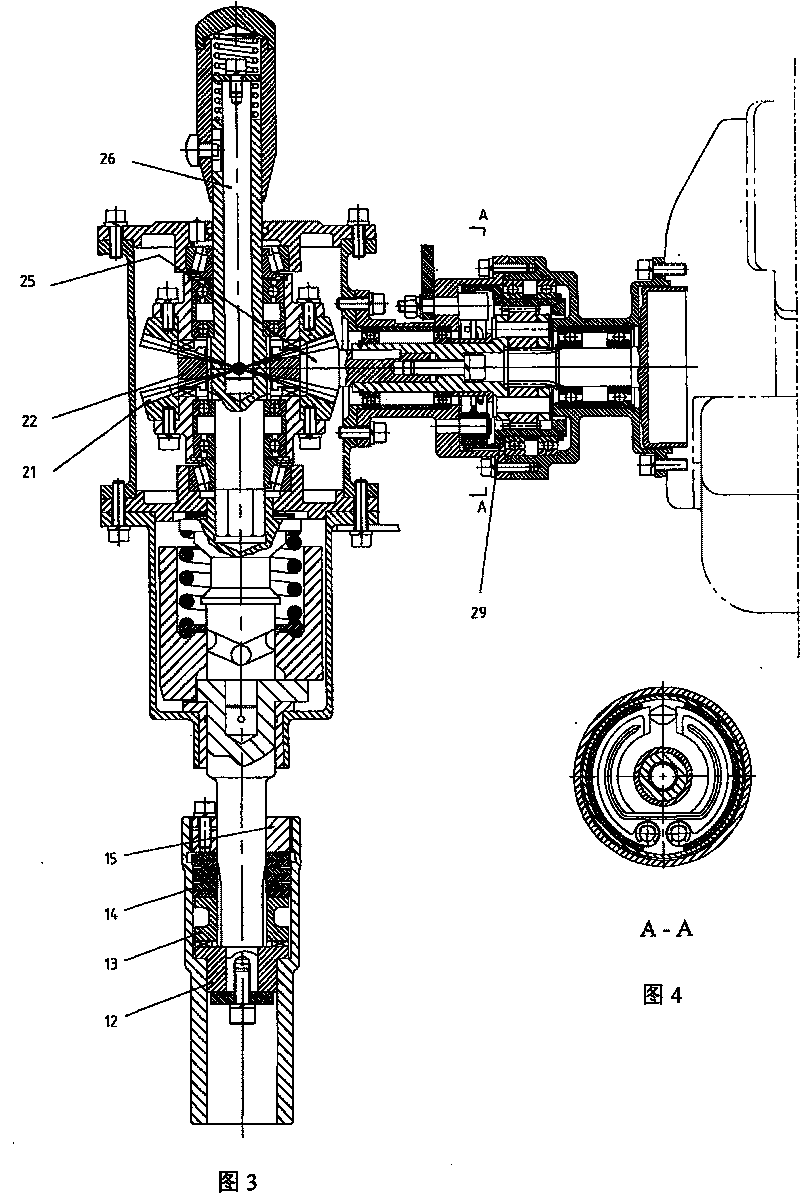
[0003] The present invention aims at the disadvantages of the above-mentioned prior art, such as large volume, heavy weight, inconvenient up and down lines, low work efficiency, high failure rate, and the tightness of the tightened nut depends entirely on manual feeling, and the torque cannot be accurately controlled. A dual-purpose wrench for a portable vehicle, which is mainly composed of a power source 6, a wrench main body 2, a reversing handle 3, a wrench sleeve 1 and an indexing operation handle 4, and the indexing operation handle 4 is fixedly connected to the handle On the hand main body 2, the wrench main body 2 is composed of a planetary gear train and a bevel gear train. The planetary gear train is connected to a gasoline engine as a power source 6, and the internal gear in the planetary gear train is controlled by a clutch handle 5. The tension / loosening of the ring 29 is used to control the power output; the reversing handle 3 on the wrench main body 2 controls the spline sleeve 22 and the two large bevel gears 21 through the mandrel 26 to realize the reversing respectively; The control structure in the wrench sleeve 1 is composed of a butterfly spring 14, an angled tooth insert 12 and a spline sleeve tooth insert 13. By adjusting the screw cap 15 to apply pressure to the butterfly spring 14, the controllable torque can be realized.

Method used


Image

  • Portable vehicle mounted dualpurpose wrench
  • Portable vehicle mounted dualpurpose wrench
  • Portable vehicle mounted dualpurpose wrench

Examples


Embodiment

[0020] The present invention uses a gasoline engine as the power source 6, which is suitable for the maintenance of railway sleeper bolts and other occasions without power supply where it is inconvenient to use a power supply or no power supply. The system is composed of two parts, through the gripping or loosening of the clutch handle 5, the tension and floating of the ring gear 29 in the planetary gear train are controlled, thereby decelerating the gasoline engine and controlling the power output; in the wrench main body 2 In the internal bevel gear train mechanism, the two large bevel gears 21 engage with the pinion gear 25 at the same time, and rotate in opposite directions. Pull up through the reversing handle 3, drive the spline sleeve 22 to combine with the upper large bevel gear 21, and pass through The reversing handle 3 is pressed down, and the driving spline sleeve 22 is combined with the lower large bevel gear 21 to achieve the reversing purpose of forward and rever...


PUM


Abstract

The invention relates to a portable and vehicle double-purpose wrench, which solves the disadvantages that the wrench volume is big, the weight is heavy, the upward and downward routes are inconvenient, the working efficiency is low, the failure rate is high, and the accurate torque control cannot be performed. A planetary wheel system and a bevel gear system are arranged inside the wrench main body (2), the planetary wheel system is connected with a power source (6) gasoline engine, and the power output of the gasoline engine is realized through the tensioning / releasing of the inner gear ring(29) of the planetary wheel system; a direction changing handle (3) is respectively meshed with a pinion through the two gears in the bevel gear system, the rotating directions of the direction changing handle and the are reverse, the direction changing handle is combined with the two gears to change direction through the spline housing (22); a butterfly shaped sprig and a tooth type component with an angle are arranged in the wrench sleeve (1), and the torque control is realized through the pressure exertion of the rotating cover to the butterfly shaped spring; the wrench main body and thetraveling bogie (10) are connected in a movable way through a parallel four-bar linkage arm (8). The invention has the advantages that the volume is small, and the weight is light; the manufacture andthe maintenance are convenient; the operation is comfortable, the failure rate is low and the working efficiency is high; the torque can be accurately controlled, and the invention reaches the technicalrequirements in the industry.

Description

Technical field: [0001] The invention relates to a mechanical wrench, in particular to a portable dual-purpose mechanical wrench suitable for maintenance of railway sleeper bolts and tightening bolts in other occasions without power supply. Background technique: [0002] At present, the mechanical wrench commonly used in railway maintenance operations is large in size and heavy in weight. It is very inconvenient to get on and off the line, and has a high failure rate, which is very unfavorable for improving work efficiency and locomotive operation. When the bolt is tightened and tightened, the tightness of the tightened nut depends entirely on manual feeling, and the torque cannot be accurately controlled, so it cannot meet the technical requirements of the industry. Invention content: [0003] The present invention aims at the disadvantages of the above-mentioned prior art, such as large volume, heavy weight, inconvenient up and down lines, low work efficiency, high failu...

Claims


Application Information

Patent Timeline
Patent Type & Authority Patents(China)
IPC IPC(8): B25B21/00B25B23/14B23P19/06
Inventor 张忠海
Owner CANDQ AMUSEMENT EQUIP CO LTD
Learn More