
Gear drive motor

A technology of gear transmission and motor, which is applied in the direction of electric components, magnetic circuit rotating parts, and control of mechanical energy. It can solve the problems of discrete positions, difficult design of gear trains, and limited range, and achieve the effect of improving the degree of freedom of configuration.

Active Publication Date: 2008-03-26
SANKYO SEIKI MFG CO LTD
View PDF1 Cites 7 Cited by
  • Summary
  • Abstract
  • Description
  • Claims
  • Application Information

AI Technical Summary

Problems solved by technology

[0004] On the other hand, in a geared motor, in order to achieve thinning, there is a type in which the plate constituting the bearing of the gear train is omitted and the bearing of the gear train is formed on the remaining part after the pole teeth forming the stator core are cut out. In a motor, such as the motor described in Patent Document 1, if the auxiliary poles are arranged at positions facing each other, the main poles with a large area are concentrated and the auxiliary poles with a small area are scattered, so that the bearings of the gear train can be formed. Discrete position, the range of configurable gear trains is limited, or the gear train must be configured avoiding the auxiliary pole
Therefore, there is a problem that it is difficult to design the configuration of the gear train in order to obtain the desired gear ratio

Method used


Image

  • Gear drive motor
  • Gear drive motor
  • Gear drive motor

Examples


Embodiment Construction

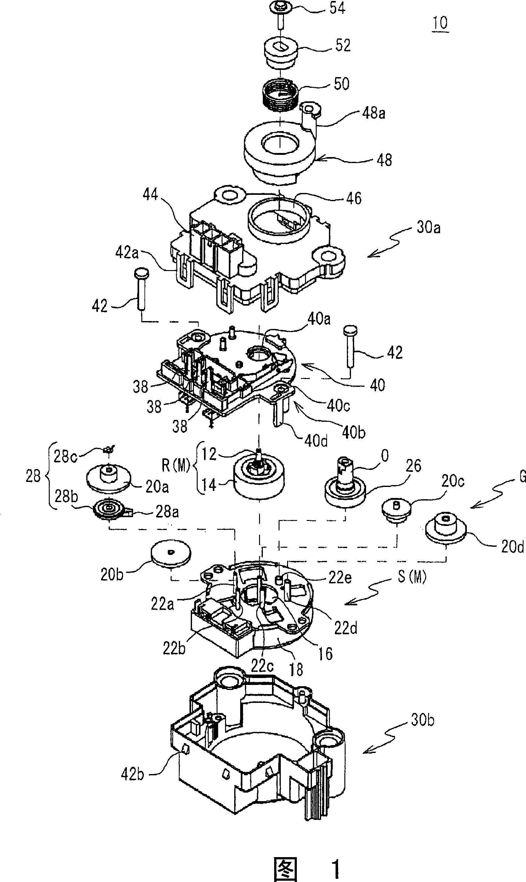
[0034] Hereinafter, a geared motor according to an embodiment of the present invention will be described in detail with reference to the accompanying drawings. FIG. 1 is an exploded perspective view showing a schematic configuration of a geared motor 10 according to an embodiment of the present invention.

[0035] As shown in FIG. 1 , a geared motor 10 according to an embodiment of the present invention is formed by accommodating a salient-pole motor M and a reduction mechanism in body casings 30 a and 30 b. The salient-pole motor M includes: around the rotating shaft 12 A rotor R formed by providing magnets; and a stator S formed by arranging a plurality of pole teeth 16, 16 . The speed reduction mechanism has a plurality of compound gears 20 a , 20 b , 20 c , and 20 d to reduce the rotation of the rotor shaft 12 of the motor M and transmit it to the output shaft 0 . The geared motor 10 decelerates the rotation supplied by the motor M to increase the rotational force, and ou...


PUM


Abstract

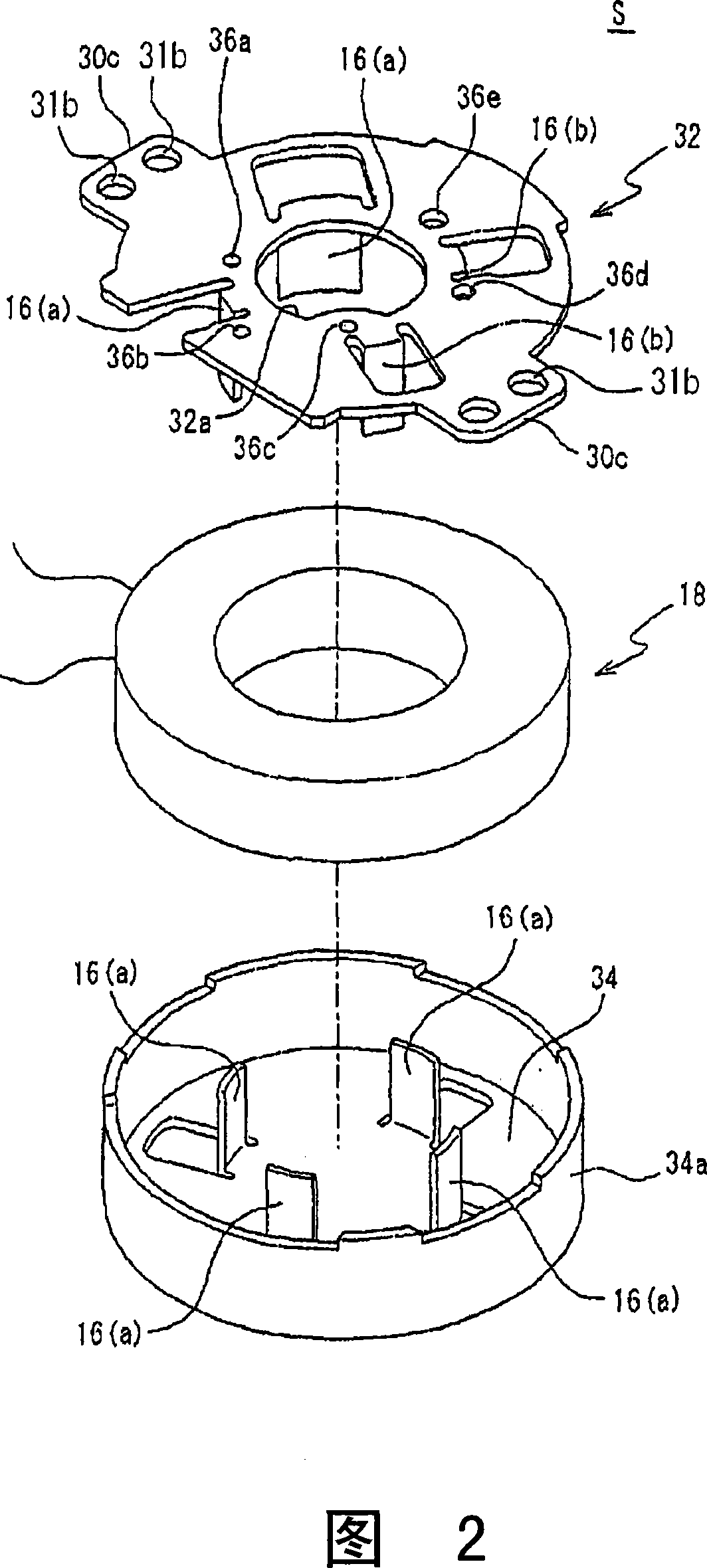
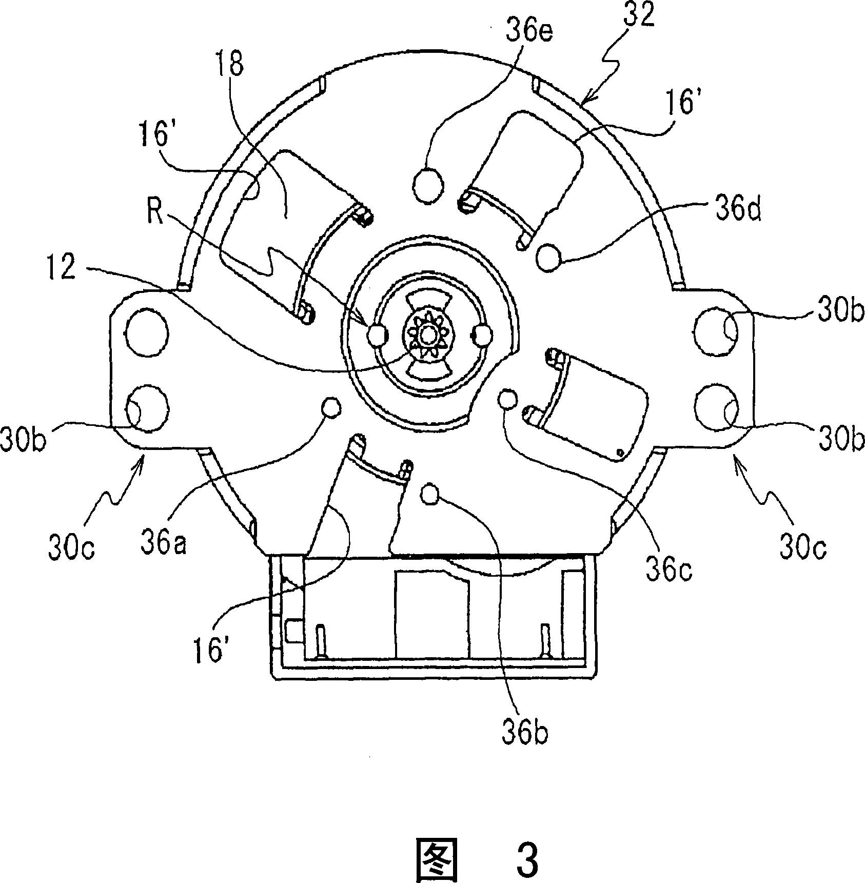
The present invention provides a geared motor capable of securing a large space for a bearing forming a gear train and increasing the freedom of arrangement of the gear train. The geared motor includes a salient pole motor having a stator including a plurality of pole teeth and a coil, and a reduction mechanism that decelerates the rotation of the motor, forming an auxiliary pole of the motor (M) The stator core (32) on one side of (16b) is provided with bearing holes (36a-36e) for holding the shafts of the gears of the gear train of the reduction mechanism (G).

Description

technical field [0001] The invention relates to a gear transmission motor, in particular to a gear transmission motor which is mainly suitable for driving mechanisms such as a drain valve of a washing machine and an opening and closing louver damper of a ventilation fan. Background technique [0002] A geared motor in which a motor and a gear train are integrally provided has been known in the past. For example, an AC synchronous motor including a stator having a plurality of pole teeth is applied to the geared motor described in Patent Document 1. These plurality of pole teeth are composed of a plurality of main poles of substantially the same shape and a plurality of auxiliary poles slightly smaller than the main pole. to disrupt the balance of the magnetic field. [0003] Patent Document 1: Japanese Patent Laid-Open No. 2002-262491 [0004] On the other hand, in the geared motor, in order to achieve thinning, there is a method in which the bearing of the gear train is ...

Claims


Application Information

Patent Timeline
Patent Type & Authority Applications(China)
IPC IPC(8): H02K1/27H02K7/116
Inventor 渡部聪一
Owner SANKYO SEIKI MFG CO LTD
Learn More