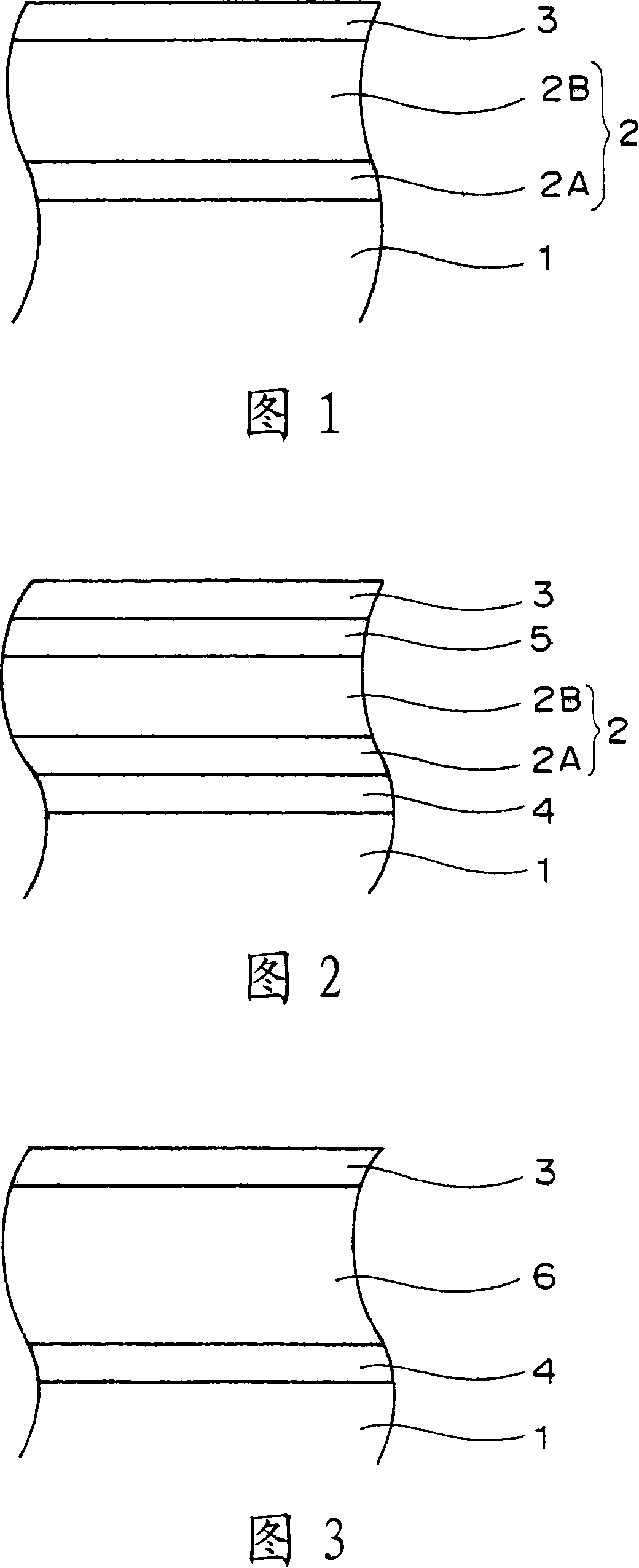
Electrophotographic photoreceptor, process cartridge and image forming device using the same
一种电子照相、成像装置的技术,应用在应用电荷图形的电记录工艺、应用电荷图形的电记录工艺的设备、光学等方向,能够解决表面附着性增大、表面层硬度低、感光体寿命缩短等问题,达到耐氧化性优异、高防水性、优异感光度的效果
- Summary
- Abstract
- Description
- Claims
- Application Information
AI Technical Summary
Problems solved by technology
Method used
Image
Examples
Embodiment 1
[0252] First, an organic photoreceptor in which an undercoat layer, a charge generating layer, and a charge transporting layer are sequentially stacked on an aluminum substrate was manufactured in the following procedure.
[0253] Formation of base coat
[0254] By stirring and mixing 20 parts by weight of a zirconium compound (trade name: ORGATICS ZC540, manufactured by Matsumoto Chemical Industry Co., Ltd.), 2.5 parts by weight of a silane compound (trade name: A1100, manufactured by Nippon Unicar Company Limited), 10 parts by weight Parts of polyvinyl butyral resin (trade name: S-LEC BM-S, manufactured by Sekisui Chemical Co., Ltd.) and 45 parts by weight of butanol are coated on the surface of an aluminum substrate with an outer diameter of 84 mm, And heating and drying at a temperature of 150° C. for 10 minutes, thereby forming an undercoat layer having a thickness of 1.0 μm.
[0255] Formation of charge generation layer
[0256] Next, by mixing 1 part by weight of chlo...
Embodiment 2
[0303] A photoreceptor (2) was obtained in the same manner as in Example 1, except that, when the electrophotographic photoreceptor of Example 1 was produced, a mixed gas of nitrogen, helium, and oxygen introduced through the gas inlet 20 The amount of the gas was changed to about 200 sccm (nitrogen gas 100 sccm, helium gas 100 sccm and oxygen gas 1 sccm) to form a surface layer.
[0304] In addition, evaluation was performed in the same manner except that, in the evaluation of Example 1, the photoreceptor (2) was used instead of the photoreceptor (1). The infrared absorption spectrum of the surface layer of the photoreceptor (2) is shown in FIG. 9 .
[0305] In Table 1 the results including the analysis of the surface layer are shown.
Embodiment 3
[0307] A photoreceptor (3) was obtained in the same manner as in Example 1, except that, in manufacturing the electrophotographic photoreceptor of Example 1, by changing the mixed gas introduced through the gas inlet 20 to nitrogen, helium, A mixed gas of hydrogen and oxygen was introduced into about 450 sccm (100 sccm of nitrogen, 150 sccm of helium, 200 sccm of hydrogen, and 0.1 sccm of oxygen) to form a surface layer.
[0308] In addition, the evaluation was performed in the same manner except that, in the evaluation of Example 1, the photoreceptor (3) was used instead of the photoreceptor (1). The infrared absorption spectrum of the surface layer of the photoreceptor (3) is shown in FIG. 10 .
[0309] In Table 1 the results including the analysis of the surface layer are shown.
PUM
 Abstract
Description
Claims
Application Information
 - R&D Engineer
- R&D Manager
- IP Professional
- Industry Leading Data Capabilities
- Powerful AI technology
- Patent DNA Extraction
Browse by: Latest US Patents, China's latest patents, Technical Efficacy Thesaurus, Application Domain, Technology Topic, Popular Technical Reports.
© 2024 PatSnap. All rights reserved.Legal|Privacy policy|Modern Slavery Act Transparency Statement|Sitemap|About US| Contact US: help@patsnap.com


