
Heating spiral rod for processing plastic machine and its manufacturing method

A technology of heating screw and manufacturing method, applied in the field of heating screw for processing plastic machines, can solve the problems of immature structure, waste of heat energy, damage to high-temperature wires of porcelain rods, etc., and achieve convenient installation and replacement, reduce production costs, and reduce maintenance. cost effect

Inactive Publication Date: 2008-03-26
林志刚
View PDF1 Cites 1 Cited by
  • Summary
  • Abstract
  • Description
  • Claims
  • Application Information

AI Technical Summary

Problems solved by technology

This design has some problems in use: the outer circle of the electric furnace wire heating ring and part of the outer circle of the machine tube are exposed, so that part of the heat energy is dissipated in the space, resulting in waste of heat energy; because this design can only be heated and plasticized through the inner hole wall of the machine tube Plastic, so that the plastic near the inner hole wall of the machine tube is plasticized faster and more fully, while the plastic farther away from the inner hole wall is slower and insufficiently plasticized
However, in the process of use, there are some problems in the technical solution of Chinese patent 95216355.1: as far as the disclosed technical solution is concerned, the structure used is not mature enough to truly realize industrialized production
If the ceramic rod is placed in the screw and there is a gap with the inner wall of the screw, then when the screw rotates, a high-temperature wire is required to drive the ceramic rod, and the high-temperature wire receives too much torque and is easily damaged.
If the ceramic rod is closely attached to the inner wall of the screw and driven by the friction of the inner wall of the screw, the diameter and dimension accuracy of the ceramic rod is required to be high. If the size is too large, it is difficult to install and replace the ceramic rod. If the size is too small, the friction between the ceramic rod and the inner wall of the screw If the force is small, the rotation frequency of the multi-level ceramic rods will be inconsistent, and the high-temperature wires in the ceramic rods will be damaged.
Moreover, if the multi-stage heating ceramic rod is directly inserted into the screw rod, the connection position of the power supply is not easy to align, and the high-temperature wire will also be damaged
Therefore, the effect is not ideal

Method used


Image

  • Heating spiral rod for processing plastic machine and its manufacturing method
  • Heating spiral rod for processing plastic machine and its manufacturing method

Examples


Embodiment 2

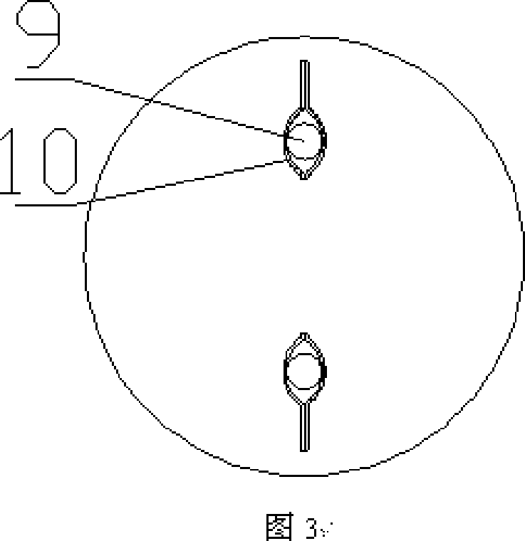
[0024] Embodiment 2 of the present invention: make hollow screw rod 1, machine pipe 11 is installed outside screw rod 1, put into 20 sections of porous refractory bricks 4 in screw rod 1, each porous refractory bricks 4 are connected in a row, on porous refractory bricks 4 A heating hole 5 is provided, and the heating hole 5 penetrates to form the long hole 3 . Make a positioning hole 6 in the middle of the porous refractory brick 4, penetrate the positioning shaft 7 in the positioning hole 6, put a plurality of porous refractory bricks 4 on the positioning shaft 7, and then the porous refractory brick 4 can be fixed. The cross sections of the positioning hole 6 and the positioning shaft 7 are regular hexagons.

[0025] Make 6 centrally symmetrical heating holes 5 on the porous refractory brick 4 . Porous refractory brick 4 is made into cylindrical shape, and length is 6 centimetres.

[0026] The heating element 2 adopts an electric furnace wire 8, and the connecting head of...


PUM


Abstract

The present invention discloses one kind of heating screw for plastic processing machine and its making process. The heating screw includes one screw, at least two sections of porous refractory bricks in one line inside the screw, and one heating element set inside the long through hole in the porous refractory bricks. The heating screw has the advantages of simple structure, easy installation, etc. It is applied in plastic pelletizing machine, plastic injection molding machine, blow molder, plastic extruding machine and other plastic processing machines.

Description

technical field [0001] The invention relates to a heating screw for a plastic processing machine and a manufacturing method thereof, and belongs to the technical field of heating screw for a plastic processing machine. Background technique [0002] In the prior art, plastic granulators, injection molding machines, blow molding machines, and extruders all adopt the design of installing electric furnace wire heating ring heating on the machine tube of the screw rod, that is, external heating. This design has some problems in use: the outer circle of the electric furnace wire heating ring and part of the outer circle of the machine tube are exposed, so that part of the heat energy is dissipated in the space, resulting in waste of heat energy; because this design can only be heated and plasticized through the inner hole wall of the machine tube Plastic, so that the plastic near the inner hole wall of the machine tube is plasticized faster and more fully, while the plastic farthe...

Claims


Application Information

Patent Timeline
IPC IPC(8): B29C45/72B29C45/60B29C47/84B29C47/60B29C48/515
CPCB29C48/515
Inventor 林志刚
Owner 林志刚
Learn More