
Electronic device with correction function and method for correcting electronic device

An electronic device, a technology for calibrating signals, applied to equipment with stored calibration coefficients, test/calibration devices, measurement devices, etc., can solve the problem of changing receiver characteristics, affecting circuit noise performance, and reducing direct down-conversion receiver 10 performance And other issues

Active Publication Date: 2008-03-19
MEDIATEK INC
View PDF0 Cites 2 Cited by
  • Summary
  • Abstract
  • Description
  • Claims
  • Application Information

AI Technical Summary

Problems solved by technology

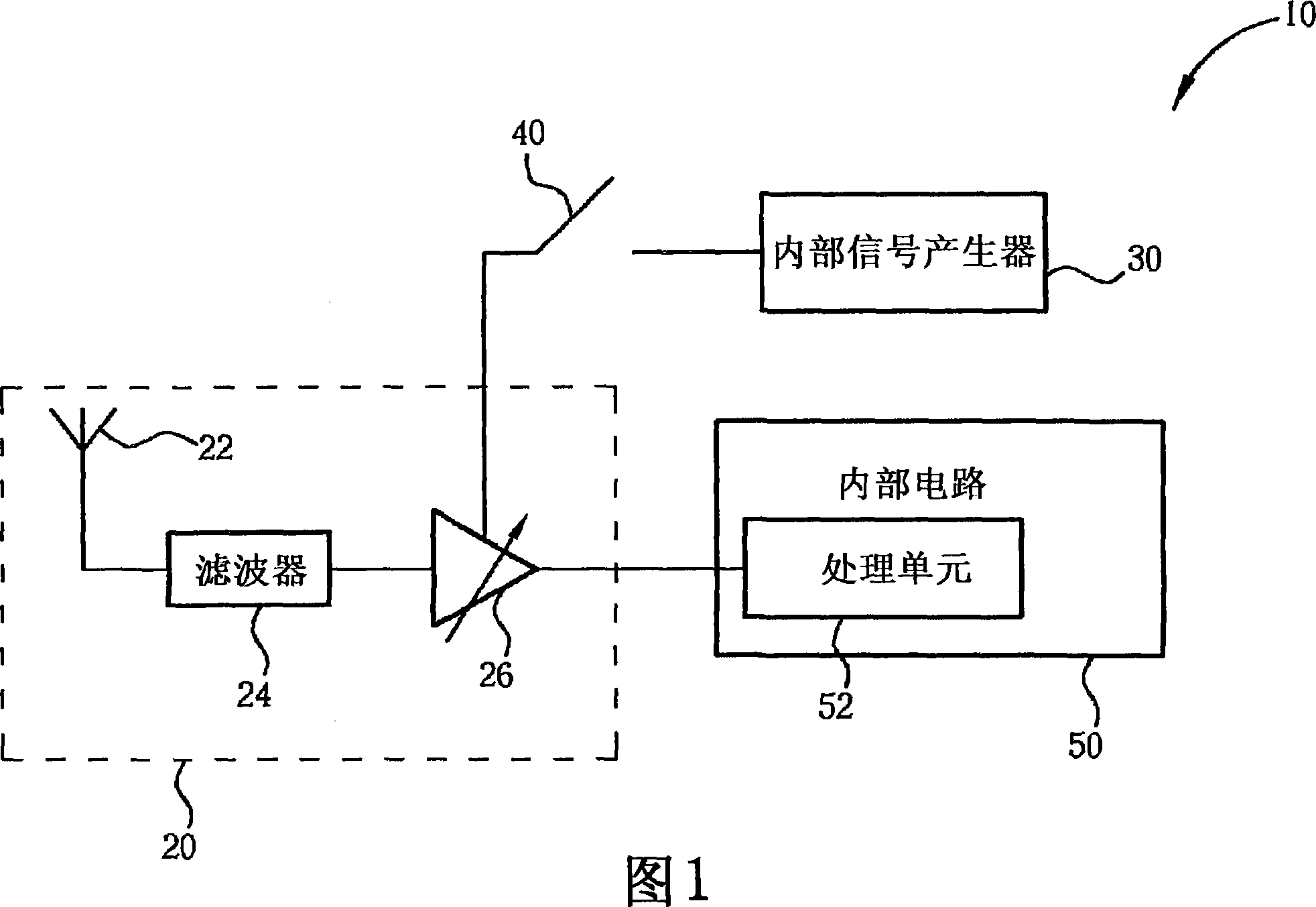
When the switch unit 40 is turned off instead of turned on, although the switch unit 40 is not in operation, it is still directly coupled to the front-end input stage 20, which will cause some parasitic resistance and parasitic capacitance to appear in the direct down-conversion receiver 10, wherein the parasitic Resistors will introduce thermal noise into the circuit, greatly affecting the noise performance of the circuit and changing the characteristics of the receiver, while parasitic capacitance will affect the input matching conditions of the front-end circuit, thus reducing the existing technology directly down-converts the performance of the receiver 10

Method used


Image

  • Electronic device with correction function and method for correcting electronic device
  • Electronic device with correction function and method for correcting electronic device
  • Electronic device with correction function and method for correcting electronic device

Examples


Embodiment Construction

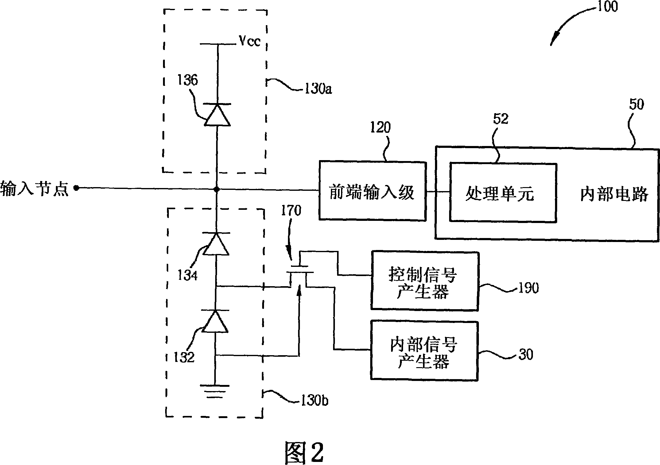
[0028] Please refer to FIG. 2 . FIG. 2 is a schematic diagram of a direct down-converting receiver 100 , which is a first embodiment of an electronic device with a calibration function provided by the present invention. The direct down-conversion receiver 100 includes a front-end input stage 120 , a plurality of ESD protection units 130 a , 130 b , an internal circuit 50 , an internal signal generator 30 , a control signal generator 190 , and a switch unit 170 . The front-end input stage 120 is used for receiving a radio frequency signal received from an input node. A plurality of ESD protection units 130a, 130b include three diodes 132, 134, 136 connected in series to V ccand ground between the two voltage supply rails (voltage supply rail). The internal circuit 50 includes a processing unit 52 . The front-end input stage 120 has the same function as the aforementioned front-end input stage 20 in the prior art. The ESD protection units 130a, 130b located at the input end o...


PUM


Abstract

The invention discloses an electronic device with calibration function and a method for calibrating an electronic device. The device includes an internal signal generator for generating a correction signal; a front-end input stage for receiving a radio frequency signal from an input node; an electrostatic discharge protection unit for protecting against electrostatic discharge; a switch unit coupled to The ESD protection unit is used to selectively transmit a correction signal to the front-end input stage, wherein due to the connection of the switch unit and the ESD protection unit, the noise performance of the direct down-converting receiver in the normal mode can be different from the matching condition Influenced by the switching unit. The advantage of the present invention is that the switching unit does not affect the performance of the receiver operating in the normal mode, and another advantage is that the correction can be generated internally through the connection of the switching unit and the electrostatic discharge protection circuit without complicated circuits Signal.

Description

technical field [0001] The present invention relates to the calibration of direct down-frequency receivers, especially an electronic device with calibration function and a method for calibrating an electronic device. Background technique [0002] The basic principle of the superheterodyne receiver is to convert the frequency band of the radio frequency signal to an intermediate frequency (IF) by mixing a radio frequency signal and a first adjustable local oscillator signal, and then mix the intermediate frequency signal and a second local oscillator signal to convert the IF signal to a baseband frequency. However, a direct conversion receiver (DCR) does not convert the radio frequency signal to the intermediate frequency signal first, but directly converts the radio frequency signal to the base frequency signal in one step. In the direct down frequency receiver, the frequency of the local oscillator signal is set to be the same as the RF signal to be converted, which means ...

Claims


Application Information

Patent Timeline
Patent Type & Authority Applications(China)
IPC IPC(8): H04B1/26H04B1/12H04L25/06
CPCH04B1/30H03F1/52H01L27/0255G01D18/008
Inventor 郭秉捷王守琮
Owner MEDIATEK INC
Learn More