
Generator transformer

A new type of generator and transformer technology, which is applied in the field of transformer manufacturing, can solve the problems of affecting the safe operation and service life of the transformer, the overall structure of the transformer is huge, and the shielding structure is complex, etc., to achieve a compact overall structure layout, reduce overheating phenomenon, and simple structural layout Effect

Active Publication Date: 2011-04-20
TBEA SHENYANG TRANSFORMER GRP CO LTD
View PDF4 Cites 0 Cited by
  • Summary
  • Abstract
  • Description
  • Claims
  • Application Information

AI Technical Summary

Problems solved by technology

[0006] In addition, in the existing generator transformers, the current transformers at the low-voltage and high-current input terminals are all installed on the single-phase sealed mother side of the generator. The single-phase single riser lead-out structure makes the overall structure of the transformer huge and not compact, and the shielding structure is complicated and the effect is not good, resulting in overheating of the product and affecting the safe operation and service life of the transformer

Method used


Image

  • Generator transformer
  • Generator transformer
  • Generator transformer

Examples


Embodiment Construction

[0043]As shown in Figures 4 to 12, an insulating cardboard 10 is provided between the upper and lower clamps 5, 6 of the transformer core 4 and the contact surface of the iron core 4, so that the upper and lower clamps 5, 6 of the iron core 4 are completely insulated, and the upper and lower clamps are fully insulated. The clips 5, 6 are connected to the iron core 4 through the ground wire, so that the upper and lower clips 5, 6 are grounded separately. The bolts at the joints of the upper beam 7, foot 9, side beam 8 of the upper and lower clamps 5, 6 and the limb plates 12, 13 of the upper and lower clamps are fully insulated with insulating sleeves 15 and insulating pads 16, and the two ends of the straps are fully insulated. It is fully insulated from the upper and lower clamps 5, 6, and then connected with a grounding wire to make the upper and lower clamps 5, 6 grounded separately. In this way, it is easy to find out if there is multi-point grounding of the iron core in a...


PUM


Abstract

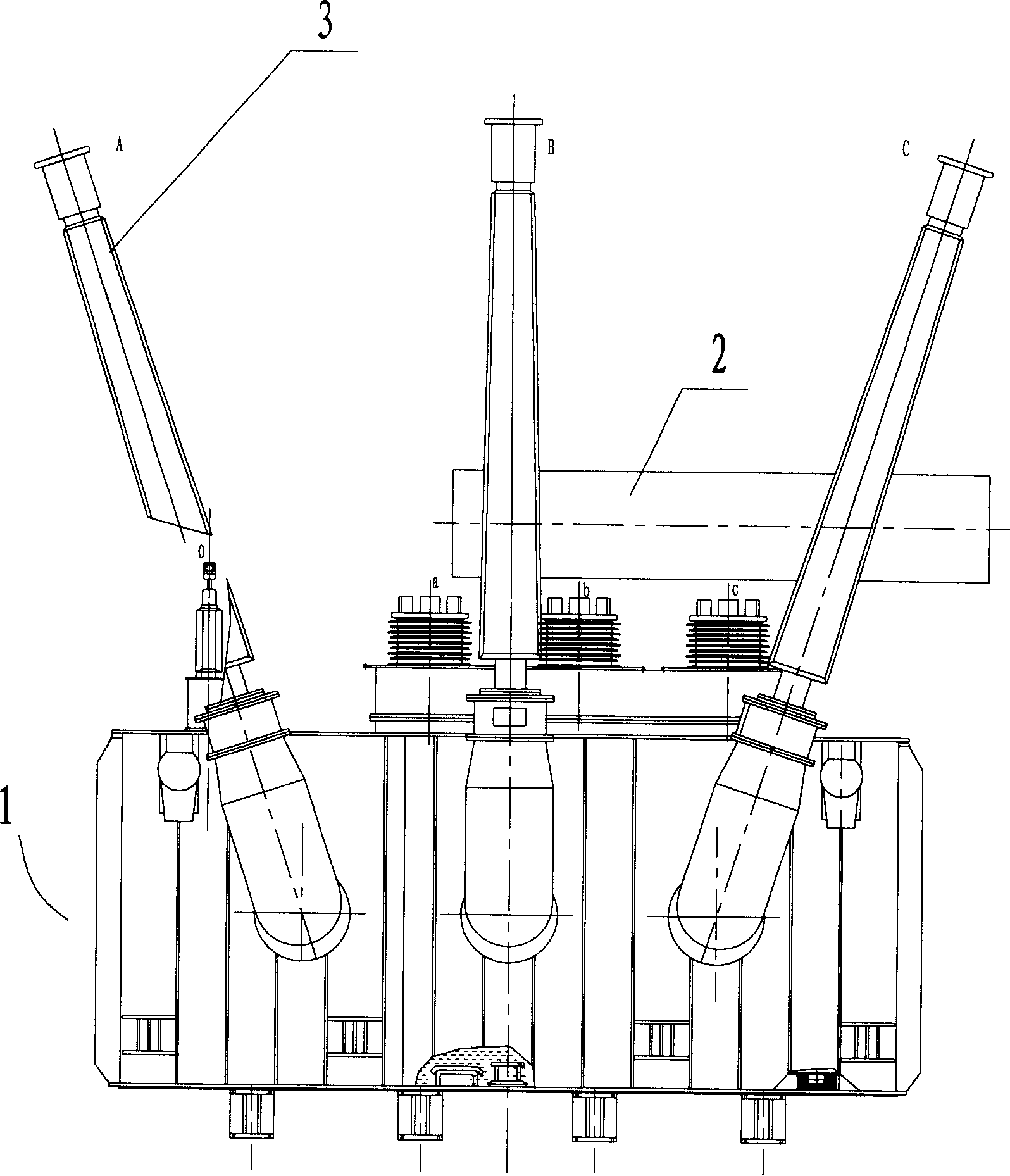
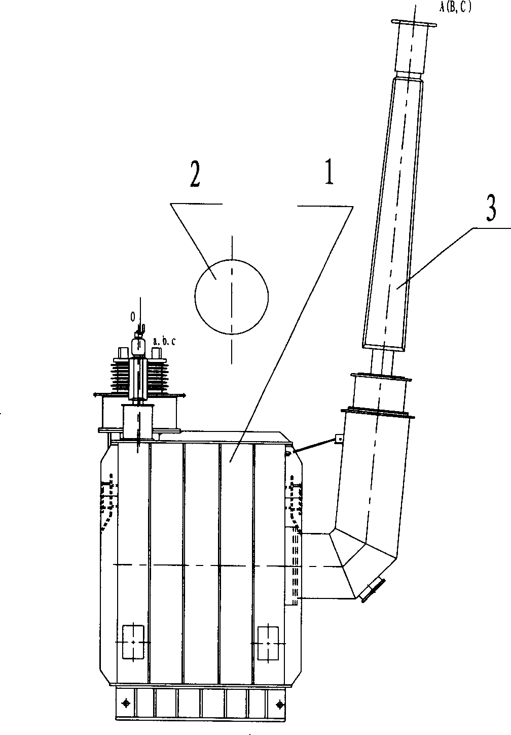
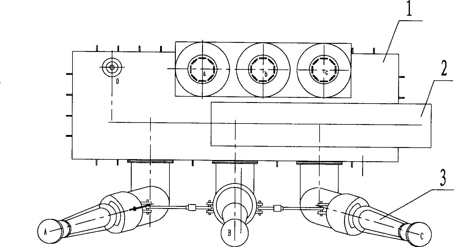
The inventing belongs to the field of transformer fabrication and specifically relates to a novel three-phase generator transformer with ultra-high capacity and high voltage. A boosting seat at the high-voltage outlet terminal of the transformer is turned at 5-15 DEG angle to the side away from the transformer. An oil reservoir is positioned above the master oil tank of the transformer in a way that the longitudinal direction of the oil reservoir is parallel to the long axis of the oil tank. An insulating paper plate is provided between the contact surfaces of the upper / lower iron core fasteners and the iron core of the transformer, thereby completely isolating the upper / lower iron core fasteners, and the upper / lower iron core fasteners are connected with the iron core by grounded wires, thereby allowing the upper / lower iron core fasteners to be grounded individually. A fastener magnetic shield is fixed on the ventral plate of each of the upper / lower iron core fasteners of the transformer by using a two-way screw bolt. A limb plate of the upper iron core fastener of the transformer is retracted inside the fastener. A suspended ring on the ventral plate of the upper iron core fastener is covered with a Cu shield on the outer surface. An iron yoke block is provided between the coil and the lower part of the oil tank inside the transformer and is provided thereon with an elongated fan-shaped oil inlet / outlet, the oil inlet / outlet being positioned above the exit of the oil tank.

Description

technical field [0001] The invention belongs to the field of transformer manufacturing, in particular to a novel generator transformer with super large capacity, high voltage and three-phase integration. Background technique [0002] At present, in order to ensure the external insulation distance in the external arrangement of the existing ultra-large capacity and high voltage transformers, the oil conservator is usually arranged outside the main body of the transformer. Although this arrangement can ensure the insulation distance, it increases the overall outer limit size of the transformer. At the same time, since the oil conservator is far away from the main body, it also increases the difficulty of supporting the oil conservator. [0003] The upper and lower clamps of the iron core of the transformer are not insulated from the upper beam, feet, side beams, and one end of the pull belt, so that they are connected as a whole through the pull plate and then connected with ...

Claims


Application Information

Patent Timeline
Patent Type & Authority Patents(China)
IPC IPC(8): H01F30/06H01F27/36H01F27/14H01F41/00
Inventor 孙勇董军郭伟
Owner TBEA SHENYANG TRANSFORMER GRP CO LTD
Learn More