
Ice maker

A technology of ice machine and ice blade, which is applied in ice making, ice making, lighting and heating equipment, etc. It can solve the problems of inability to produce fine ice chips, affect the effect of ice scraping, and the effect of ice scraping is not good, and reach the size of ice flakes Uniformity, good ice breaking effect, and the effect of improving ice scraping ability

Inactive Publication Date: 2008-03-19
中机西南能源科技有限公司
View PDF0 Cites 3 Cited by
  • Summary
  • Abstract
  • Description
  • Claims
  • Application Information

AI Technical Summary

Problems solved by technology

Yet, because there is an opening 34 on the top of the drip tray, sometimes a part of water, especially the water splashed by the wall of the ice maker, does not flow or drip onto the drip tray, so this part of water may pass through the water tray. The opening 34 at the top of the pan falls into the bottom of the drip tray and mixes with the ice, which will cause the broken ice to stick together and affect the use of the ice
[0007] (3) What the existing ice machine usually adopts is a spiral ice scraper, and the cone angle of the ice scraper teeth on the spiral ice scraper is 30°, 36°, 45°, and the ice scraper with this angle exists The main disadvantages are: unreasonable force, poor ice scraping effect; easy to trap ice in the spiral groove, so that the ice on the inner wall of the ice bucket is not easy to fall, and also affects the ice scraping effect
[0008] (4) The spiral ice scraper can only produce flake ice, but not fine ice chips, so its use is limited

Method used


Image

  • Ice maker
  • Ice maker
  • Ice maker

Examples


Embodiment Construction

[0038] The ice maker of the present invention will be further described below in conjunction with the accompanying drawings and specific embodiments, so as to help understand the content of the present invention.

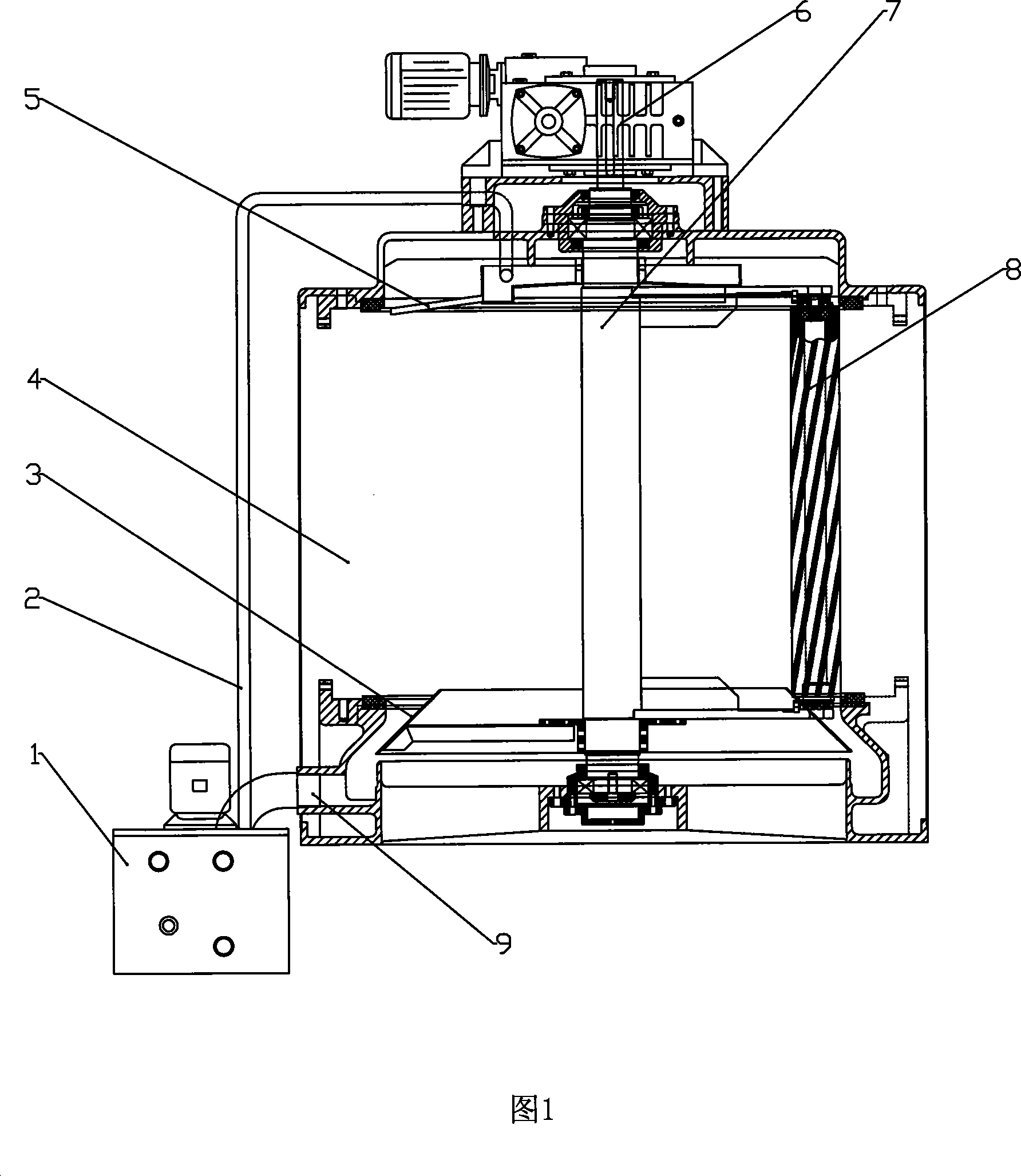
[0039] As shown in Figure 1, the ice machine includes a water tank 1, a water pump, and a water supply pipe 2 installed on the water outlet of the water pump, a water receiving tray 3, a cylindrical refrigeration evaporator 4, a water diffuser 5, a reducer 6, a main shaft 7, a water receiving Disk 8.

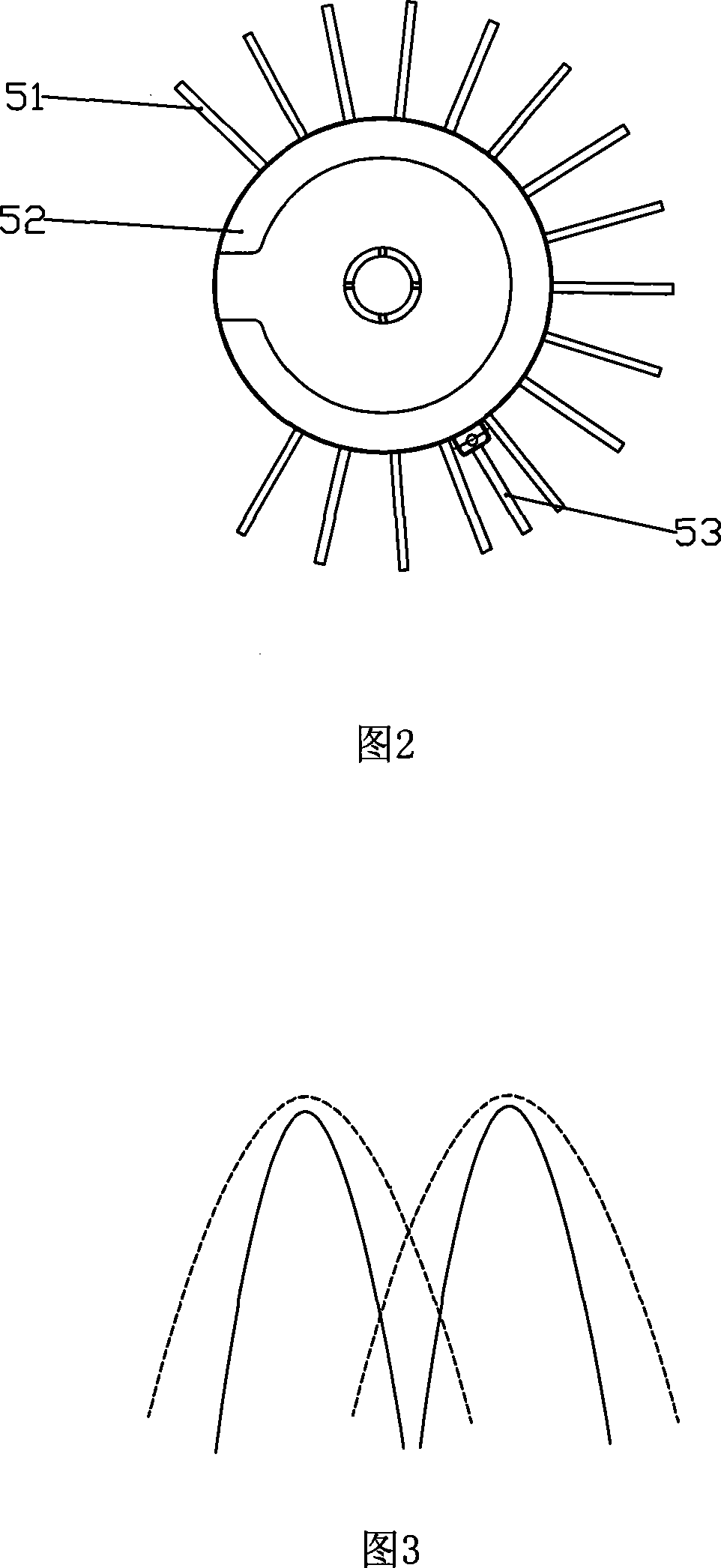
[0040] As shown in Figure 2, the water diffuser is composed of a plurality of radially arranged water diffusers 51 of equal length, which are radially distributed and welded on the same height (or bottom) of the side wall (or bottom) of the round water plate 52, and the whole water diffuser is installed on the Ice machine barrel refrigeration evaporator top position. The included angles between adjacent water pipes 51 are the same except that there is no water pipe p...


PUM


Abstract

The invention discloses an ice making machine, which comprises an ice scraper, a water containing plate and a water penetration plate installed at the top of the tube type refrigeration evaporator of the ice making machine. The invention is characterized in that the water penetration plate consists of a disc shape water plate and a plurality of water penetration pipes which are installed at the same installation height with the water plate, except the position corresponding to the ice scraper, the included angle between the adjacent water penetration pipes is the same, each water penetration pipe is inclined downwards from the end of an water inlet opening to the end of a water outlet opening, and all water penetration pipes and the axle center line of the tube type refrigeration evaporator form the same included angle. The thickness of the ice made by the ice making machine is even.

Description

technical field [0001] The present invention relates to an ice maker. Background technique [0002] The ice machine is an artificial ice-making equipment that uses refrigeration technology. Through the direct evaporation of the refrigerant, the heat carried by the water is taken away to cool the ice. Its ice-making speed is much faster than that of brine indirect ice. Ice technology. The earliest rapid ice-making was carried out in a pool with a vertical evaporation tube. After the pool water was frozen, hot air was used to melt the ice, and then water was injected into the pool, and the ice made floated on the pool; later, finger-shaped evaporation was introduced. The barrel-type rapid ice making of the device makes the ice machine step into the stage of installation. After years of development, the ice machine has become a mature and fast ice-making technology. The current development of fast ice machines not only has a variety of varieties, lower unit energy consumptio...

Claims


Application Information

Patent Timeline
IPC IPC(8): F25C1/14
Inventor 周国均刘楷刘喜峰
Owner 中机西南能源科技有限公司
Learn More