
Hollow shaft rotating stamping compression rotor based on shock compress technique

A compression technology, ram compression technology, which is applied in the field of hollow shaft rotary ram compression rotors, can solve the problems of no essential influence on the power-to-weight ratio of gas turbines, large volume and weight of the compression system, and reduced overall compression efficiency, and achieve light weight and high compression efficiency High, high boost ratio effect

Inactive Publication Date: 2008-03-12
DALIAN MARITIME UNIVERSITY
View PDF0 Cites 4 Cited by
  • Summary
  • Abstract
  • Description
  • Claims
  • Application Information

AI Technical Summary

Problems solved by technology

Axial flow compression has high single-stage compression efficiency, wide application, and mature technology, but its single-stage pressure ratio is low, multi-stage compression is required to achieve high pressure ratio, the volume and weight of the compression system are large, and the total compression efficiency is reduced; centrifugal compression single-stage compression Relatively high, relatively stable performance, but its efficiency is low
The above two airflow compression methods can also be used in combination, but it has no essential effect on improving the power-to-weight ratio of the gas turbine

Method used


Image

  • Hollow shaft rotating stamping compression rotor based on shock compress technique
  • Hollow shaft rotating stamping compression rotor based on shock compress technique
  • Hollow shaft rotating stamping compression rotor based on shock compress technique

Examples


Embodiment Construction

[0018] The present invention is described in further detail below in conjunction with accompanying drawing:

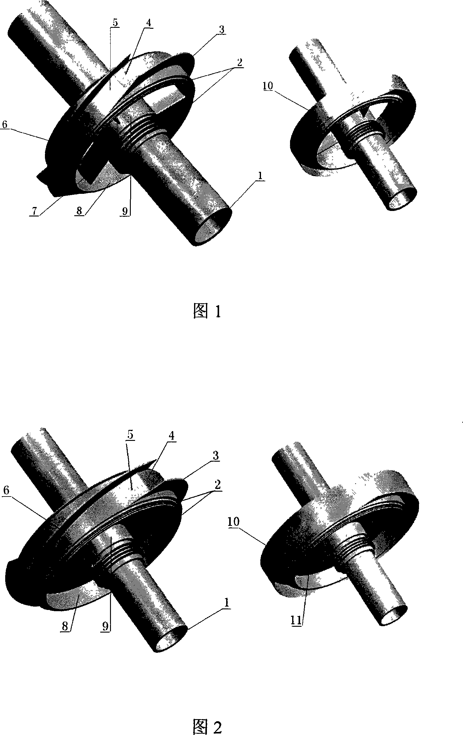
[0019] The hollow-shaft rotary stamping compression rotor based on the shock wave compression technology of the present invention is designed on the basis of the shock wave compression technology in the supersonic inlet channel and the fusion of the traditional axial flow compressor and centrifugal compressor design technology, based on the shock wave compression The advanced rotary stamping compression rotor adopts a hollow shaft design, which can greatly reduce the structural weight of the compression rotor, and can free up a certain space for installing other equipment in the hollow shaft, so that the compression rotor has a compact structure.

[0020] As shown in Figures 1 to 3, the web 12 in Figure 3 has a certain number of holes on the solid disk 11 in Figure 2. The purpose of this is to further reduce the weight of the compression rotor. It can be a round hole o...


PUM


Abstract

The invention relates to a hollow shaft rotation stamping compression rotor based on the shock compression technology, belonging to the gas turbine field, which comprises a hollow shaft, a sealing device, a wheel disc and a gas inlet flow channel on the outer edge of the wheel disc; wherein the wheel disc and the hollow shaft are made into a whole or the wheel disc is connected with the hollow shaft through a connecting key or a bearing; the outer edge of the wheel disc is provided with a certain amount of gas inlet flow channels, the gas inlet flow channel is composed of the outer edge of the wheel disc, a partition board arranged on the outer edge of the wheel disc, a gas flow contraction surface, a subsonic diffuser and an outer casing; the wheel disc and the hollow shaft of the gas inlet end and the gas outlet end of the compression rotor are provided with the sealing device. When the compression rotor rotates with the enough high speed, the gas flow is sucked into the gas inlet flow channel and discharged through the multi-shock produced by the gas flow contraction surface and the pressurization of the subsonic diffuser. The invention has the advantages of the high pressurization ratio, the high compression efficiency, the simple and compact structure, the small volume, the light weight, the low manufacturing cost, the convenient disassembly and assembly, the easy maintenance and the high reliability.

Description

technical field [0001] The invention relates to the field of gas turbines, in particular to a hollow-shaft rotary stamping compression rotor based on shock wave compression technology used in various gas turbines. Background technique [0002] The compression system, namely the compressor, is one of the three major components of a gas turbine. Its function is to compress the airflow entering the engine to obtain air at a suitable temperature and pressure. The pressure ratio and compression efficiency of the compressor will directly determine the cycle efficiency and power of the gas turbine, while its volume and weight will largely affect the power-to-weight ratio of the gas turbine. At present, the airflow compression methods commonly used in gas turbines mainly include axial flow compression, centrifugal compression and hybrid compression. Axial flow compression single-stage compression has high efficiency, wide application, and mature technology, but its single-stage pre...

Claims


Application Information

Patent Timeline
Patent Type & Authority Applications(China)
IPC IPC(8): F04D29/26F04D29/08
Inventor 钟兢军韩吉昂
Owner DALIAN MARITIME UNIVERSITY
Learn More