Stop valve

A globe valve and valve stem technology, applied in the direction of lift valve, valve device, engine components, etc., can solve the problems of the globe valve is not closed tightly, the switch is not flexible enough, the grinding groove is closed, etc., to achieve less maintenance, avoid spiral type movement, the effect of reducing friction

Inactive Publication Date: 2008-03-05
金德管业集团有限公司
View PDF0 Cites 7 Cited by
  • Summary
  • Abstract
  • Description
  • Claims
  • Application Information

AI Technical Summary

Problems solved by technology

[0003] First of all, due to frequent actions and water corrosion, the thread on the valve stem is easy to wear, which can cause the valve stem to fail in a short time, so that the shut-off valve is not closed tightly.
[0004] Secondly, the seal between the valve stem and the gland of ordinary globe valves usually uses packing. If the gland is pressed too tightly, the switch will not be flexible enough, even to the extent of labor. If the gland is pressed a little bit looser, water or other media will emerge from the upper end of the gland
[0005] Another point is that the installation of the gasket between the valve core and the valve seat of the ordinary globe valve only needs to ensure that the gasket is on a flat surface. It deforms quickly or wears out groove marks and the closure is not tight, and it cannot play the role of cut-off
[0006] In practice, when there is a problem with the stop valve, it has to be replaced. Even repair is a temporary expedient measure. Sometimes both replacement and repair must be operated under pressure, which adds a certain degree of difficulty virtually.

Method used


Image

  • Stop valve
  • Stop valve
  • Stop valve

Examples


Embodiment 1

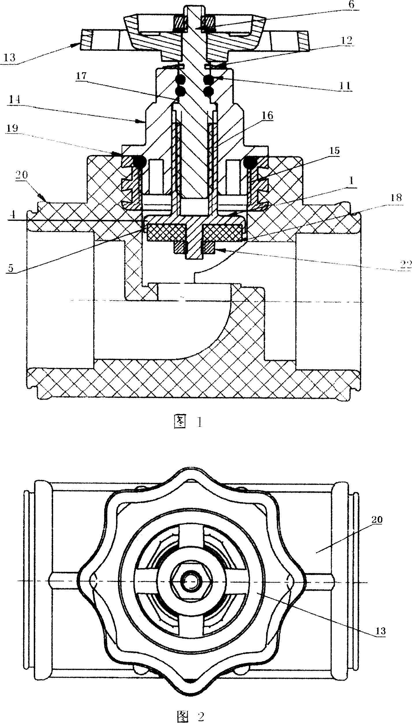
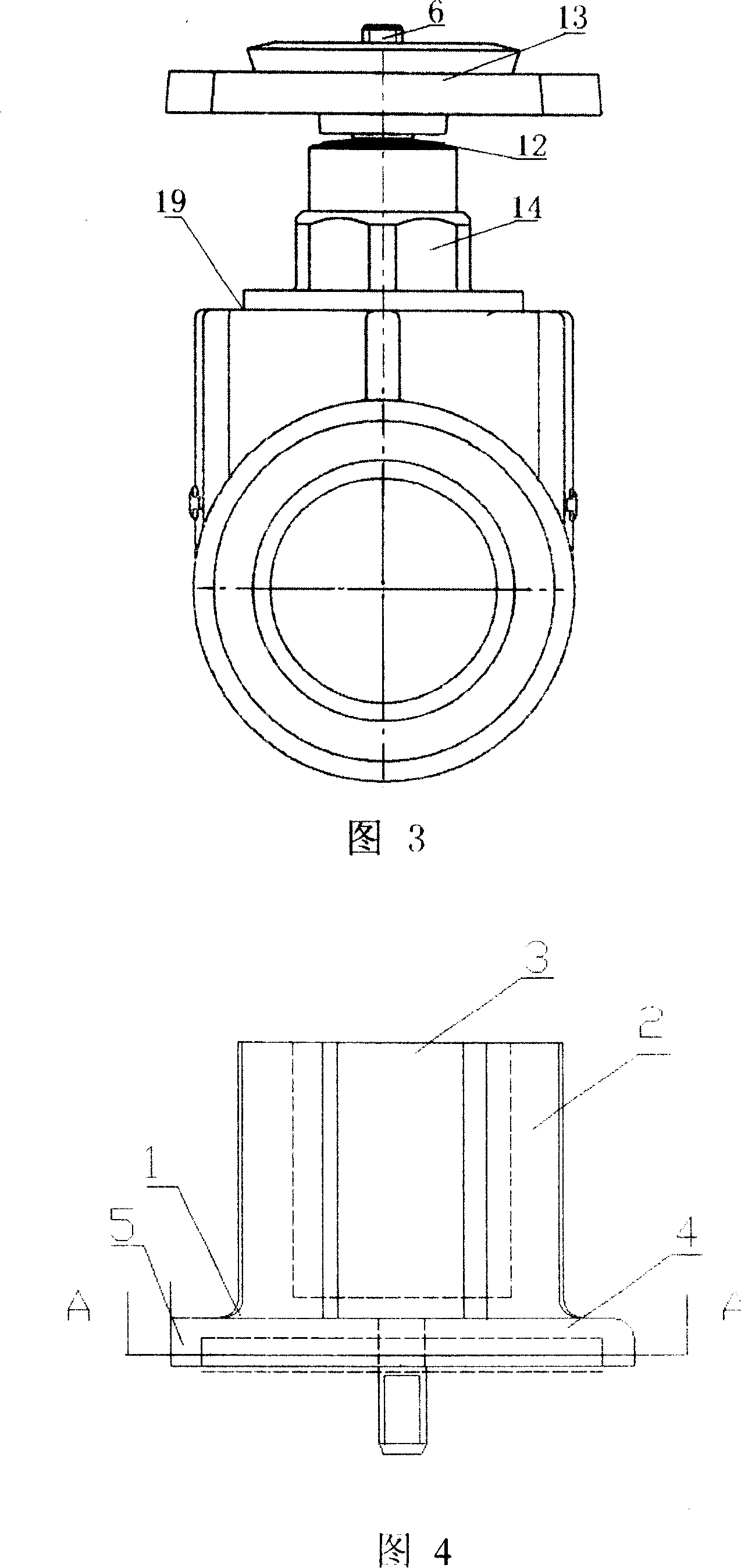
[0027] A globe valve, comprising a valve body 20, a gland 14, a valve stem 6, and a valve core 1, the valve stem 6 is threadedly connected to the valve core 1 and penetrates into the upper hole 17 of the gland 14, and is installed together with the gland 14 On the upper port 19 of the valve body 20, as shown in Figure 1-7.

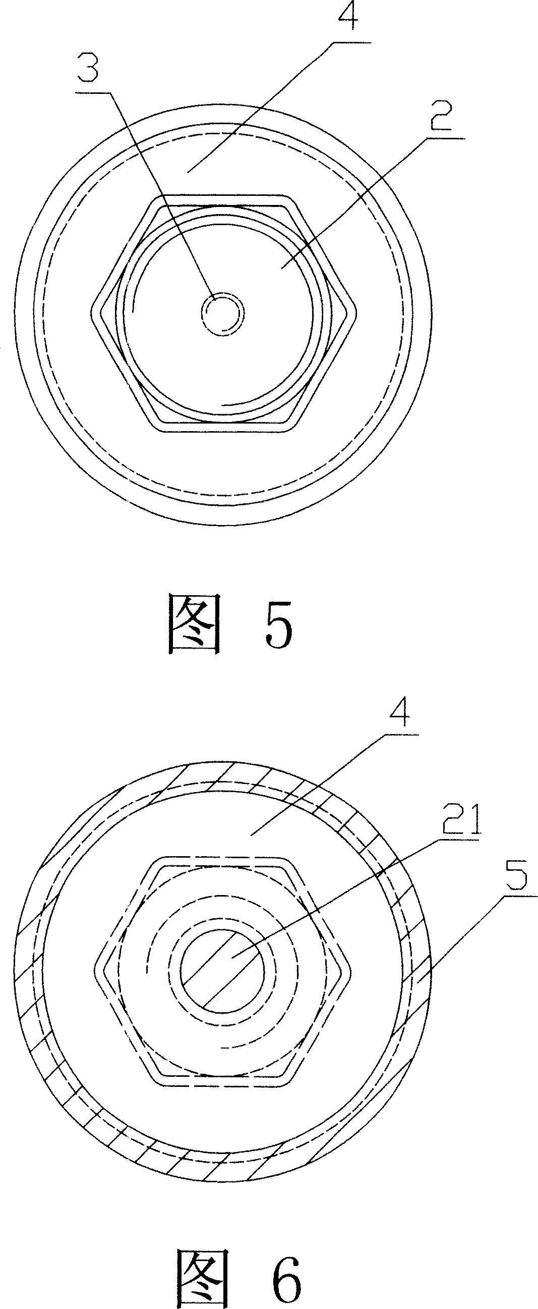
[0028] The upper part of the valve core 1 is a hexagonal prism 2, the upper center of the hexagonal prism 2 is provided with a screw hole 3, the lower part of the valve stem 6 is a thread 7, and the valve stem 6 is threadedly connected with the screw hole 3 at the center of the upper end of the valve core 1, the valve The rod 6 is connected with the valve core 1 and penetrates the hexagonal prism-shaped hole 16 at the bottom of the gland 14 and the round hole 17 at the top of the gland 14. The upper end of the valve stem 6 is provided with a thread 8 and is threadedly connected with the handwheel 13. The bottom is provided with an annular positioning groov...

Embodiment 2

[0035] As shown in Figures 8-9, the second embodiment is basically the same as the first embodiment in terms of structure, the difference is that the upper part of the valve core 1 is a hexagonal prism 2 is set as a triangular prism, and the lower end of the gland 14 is correspondingly provided with three The prism-shaped hole and the triangular prism-shaped valve core 1 are installed in the triangular-prism-shaped hole, and the rest are the same as the first embodiment.


PUM


Abstract

This invention is a globe valve. It includes valve body, valve stem, valve core and polygon prism. The polygon prism is at upper part of valve core and has screw at the center of superior end. The valve stem and valve core are connected. They are located at the upper opening of valve body with gland. The inferior end of valve core has plate shaped support, which peripheral flange is downwards. There is screw stem at the center of plate shaped support. The screw stem passes through gasket, which firmly attaches to the plate shaped support. The periphery of gasket is embedded inside the support flange. The inferior end of the gland has the hole of polygon prism. The polygon prism valve core is arranged in the hole and can slide upwards and downwards. The valve core is triangular prism that can stop rotation. This invention avoids the spiral mode of motion of normal globe valve and decreases the combined face friction between gasket and valve support. It also increases the life span of the globe valve and reduces water leaking accident.

Description

(1) Technical field [0001] The invention relates to a water heating pipe fitting, in particular to a cut-off valve. (2) Background technology [0002] Globe valves are frequently used components in plumbing pipelines and process pipelines of petrochemical enterprises. Due to the frequent switching, the common globe valves commonly used at present have defects and problems that cannot be underestimated. [0003] First of all, due to frequent actions and water corrosion, the thread on the valve stem is very easy to wear, which can cause the valve stem to fail in a short period of time, so that the shut-off valve is not closed tightly. [0004] Secondly, the seal between the valve stem and the gland of ordinary globe valves usually uses packing. If the gland is pressed too tightly, the switch will not be flexible enough, even to the extent of labor. If the gland is pressed a little bit looser, water or other media will emerge from the top of the gland. [0005] Another point ...

Claims


Application Information

Patent Timeline
Patent Type & Authority Applications(China)
IPC IPC(8): F16K1/02F16K1/36F16K1/48
Inventor 王仁强张钊崔玉珠孙丽娜
Owner 金德管业集团有限公司
Why Eureka
Try Eureka