
Spherical tooth type universal coupling

A universal coupling and semi-coupling technology, applied in the direction of couplings, elastic couplings, mechanical equipment, etc., can solve problems such as poor sealing and lubrication, limited torque transmission, and unstable angular velocity, etc., to achieve The effect of large torque transmission, reduced contact stress, and increased force-bearing contact area

Inactive Publication Date: 2008-03-05
郭太利
View PDF2 Cites 4 Cited by
  • Summary
  • Abstract
  • Description
  • Claims
  • Application Information

AI Technical Summary

Problems solved by technology

The structure of the cross shaft universal joint is simple, but it has the disadvantages of small transmission torque and unstable angular velocity. The slider type universal joint can transmit large torque, but its volume is large, and the slider and the flat head are in surface contact. , easy to wear, and both have the disadvantages of poor sealing and lubrication, which affect the service life
Ball cage type universal coupling can overcome the above defects. This coupling is composed of a ball joint and a ball hinge. Steel balls are installed between the ball joint and the ball hinge, which can transmit large torque and realize constant speed transmission. It is suitable for high-speed rotation, but its production is difficult, its processing precision is high, and its cost is high, which limits its popularization and application
The drum-shaped gear universal coupling is made of internal and external teeth meshing with each other, and the power is transmitted through the contact of the tooth surface. Generally, the internal teeth are involute straight teeth, and the external teeth are involutes that are drum-shaped along the axial direction. The swing angle of the shaped teeth meets the requirements of the intersection angle of the axes of the two transmission shafts. In the working state, the inner and outer teeth are in partial line contact along the axial direction of the teeth. The contact stress is large, which limits the transmission of torque, and the wear speed is fast, which affects the service life.
A toothed universal joint with the patent number ZL03235201.8 and a curved ball universal joint with the patent number ZL03235200.X have improved the above structure, but still have not solved the above problems

Method used


Image

  • Spherical tooth type universal coupling
  • Spherical tooth type universal coupling
  • Spherical tooth type universal coupling

Examples


Embodiment Construction

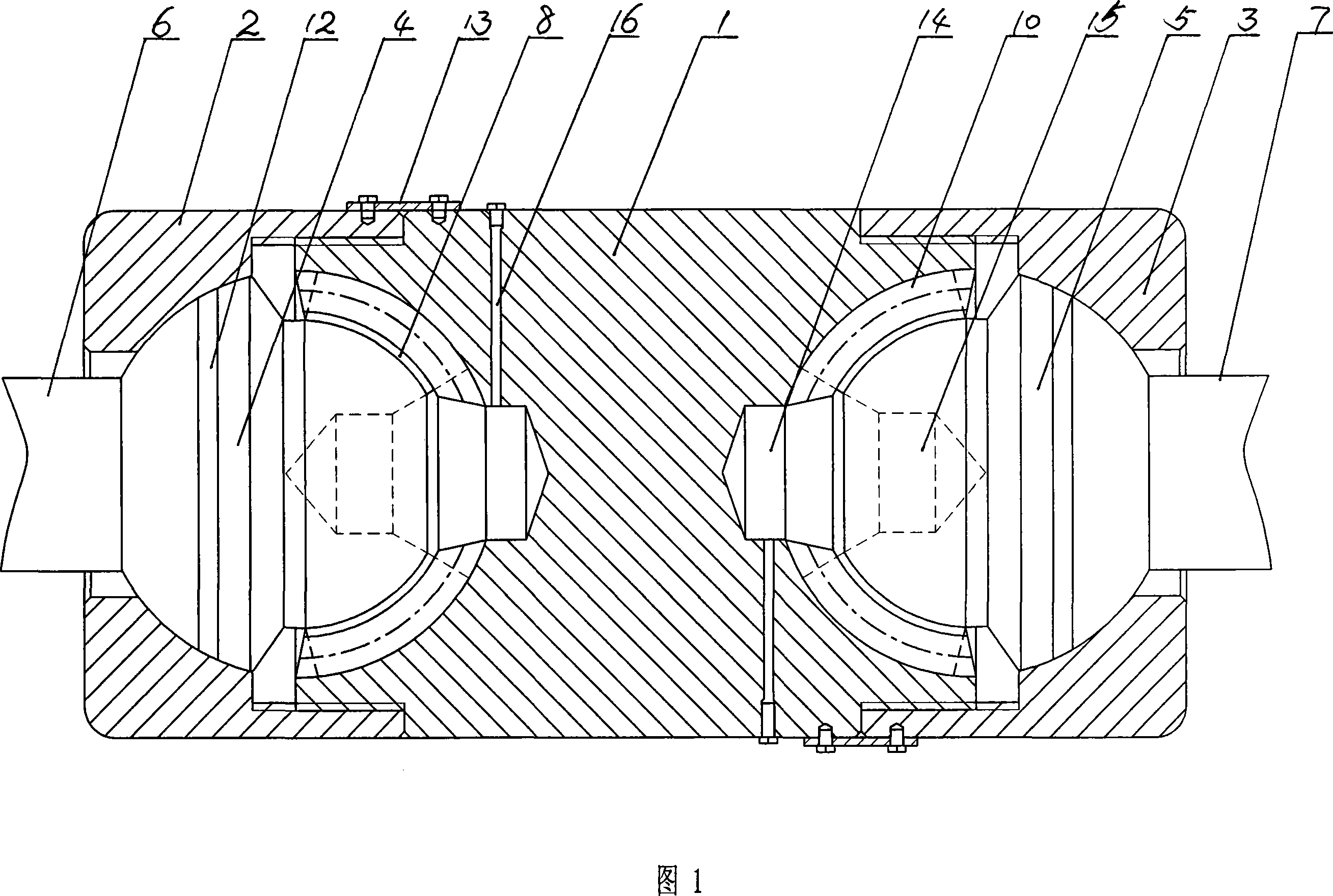
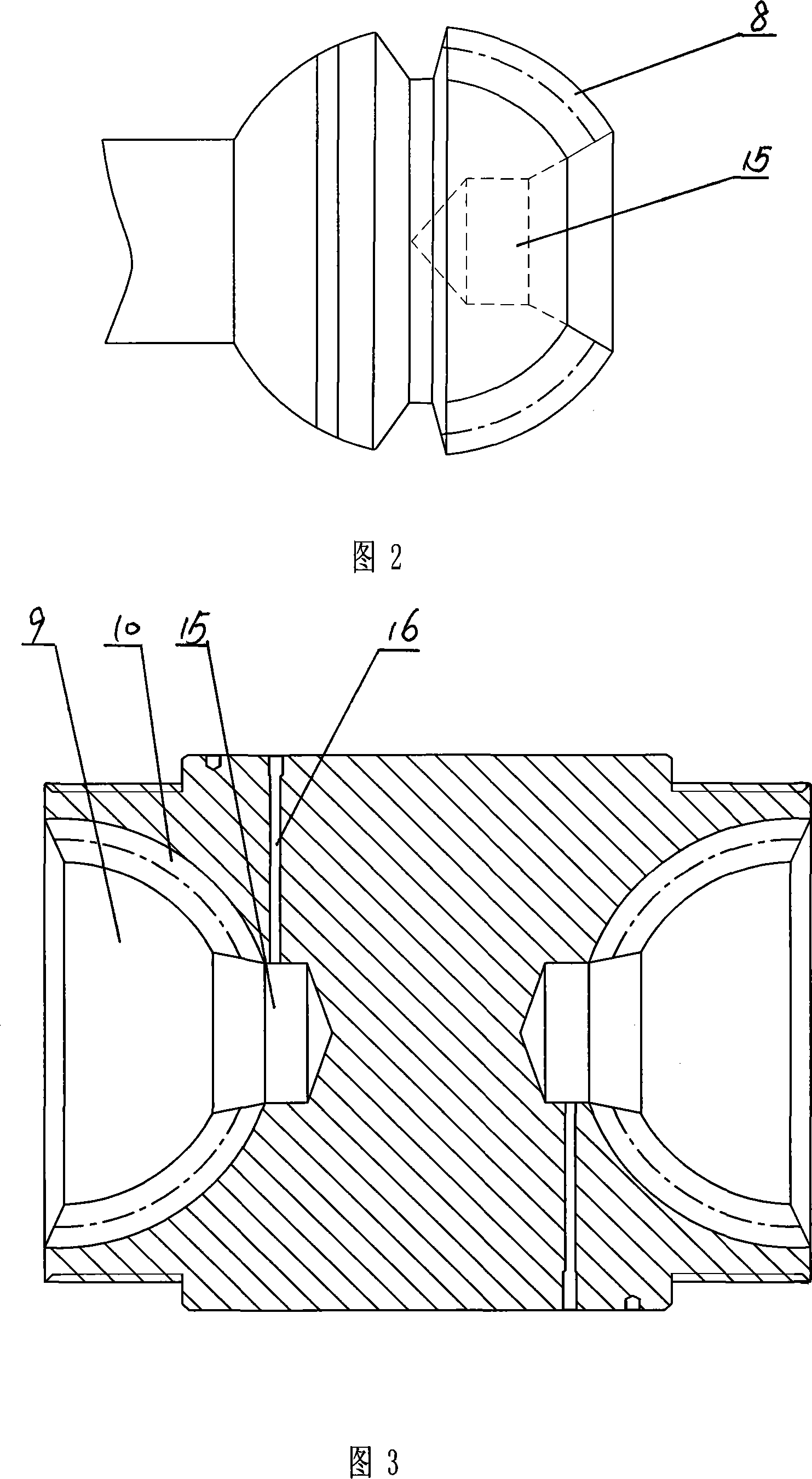
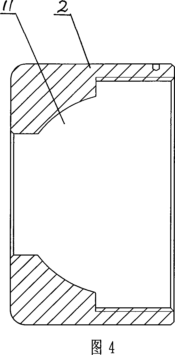
[0014] In the embodiment shown in the accompanying drawings, the spherical tooth type universal coupling of the present invention has a symmetrical structure at both left and right ends. It includes an intermediate coupling shaft 1, and the two ends of the intermediate coupling shaft 1 are respectively processed with hemispherical spherical grooves 9, and the end caps 2 and 3 connected to the two ends of the intermediate coupling shaft 1 are respectively installed in the spherical groove 9. Half-couplings, the said half-couplings are spherical ball joints 4 and 5 connected to the power input end 6 and the power output end 7 respectively, and the front hemispherical surfaces of the ball joints 4 and 5 are evenly processed. The convex arc-shaped teeth 8 are processed in the spherical groove 9 with the concave arc-shaped teeth 10 meshing with the convex arc-shaped teeth 8 on the ball joints 4 and 5, and the combination transmits torque. The inner cavities of the end caps 2 and 3 ...


PUM


Abstract

The ball-tooth universal coupler comprises a left-right symmetric intermediate joint axle and two half-couplers mounted on the two ends of the intermediate joint axle through end caps. The said half coupler is a ball-shape ball joint connected respectively with the power input end and the power output end. At the front half sphere of the ball joint are provided with several bars of externally convex arc teeth, and in the sphere recess at the two ends of the intermediate joint there is provided with internal concave arc teeth. The internal cavity of the end cap is a spherical recess corresponding to the rear sphere of the ball joint, and the ball joint is mounted movably in the ball-shape cavity formed by the end cap and the intermediate joint. Advantages: reduced contact stress to stress surface, high transfer torque, stable operation, good sealing and lubricating effect, long service life, compact structure and convenient maintenance.

Description

technical field [0001] The invention relates to an elastic coupling, in particular to a universal joint. Background technique [0002] Universal couplings are used to connect two shafts whose axes are not on the same straight line, and are widely used in power transmission in metallurgy, engineering, mining and heavy machinery industries. There are many forms of existing universal joints, such as cross shaft universal joints, slider universal joints, ball cage universal joints and drum gear universal joints, etc. . The structure of the cross shaft universal joint is simple, but it has the disadvantages of small transmission torque and unstable angular velocity. The slider type universal joint can transmit large torque, but its volume is large, and the slider and the flat head are in surface contact. , easy to wear, and both have the disadvantages of poor sealing and lubrication, which affect the service life. Ball cage type universal coupling can overcome the above defect...

Claims


Application Information

Patent Timeline
Patent Type & Authority Applications(China)
IPC IPC(8): F16D3/16
Inventor 郭太利
Owner 郭太利
Learn More