
Reactor for the continuous and simultaneous production of different polyester products having adjustable variable viscosity, the progress of the process being regulated via the hydraulic drive system

A technology for a hydraulic system and a reactor, applied in the field of reactors, can solve the problems of process adjustment of process parameters for rotor operation, unsatisfactory driving device, and expensive rotor structure, etc., so as to improve operation safety and reduce quality. , the effect of increasing strength

Active Publication Date: 2008-02-20
EPC工程与技术有限公司
View PDF3 Cites 3 Cited by
  • Summary
  • Abstract
  • Description
  • Claims
  • Application Information

AI Technical Summary

Problems solved by technology

[0017] No measures for the use of process parameters from rotor operation and their impact on process regulation were found in all investigated documents
In addition, the use of heavy drives with a large distance between the center of gravity and the reactor end is unsatisfactory or the construction of the rotor is often expensive

Method used


Image

  • Reactor for the continuous and simultaneous production of different polyester products having adjustable variable viscosity, the progress of the process being regulated via the hydraulic drive system
  • Reactor for the continuous and simultaneous production of different polyester products having adjustable variable viscosity, the progress of the process being regulated via the hydraulic drive system
  • Reactor for the continuous and simultaneous production of different polyester products having adjustable variable viscosity, the progress of the process being regulated via the hydraulic drive system

Examples


Embodiment Construction

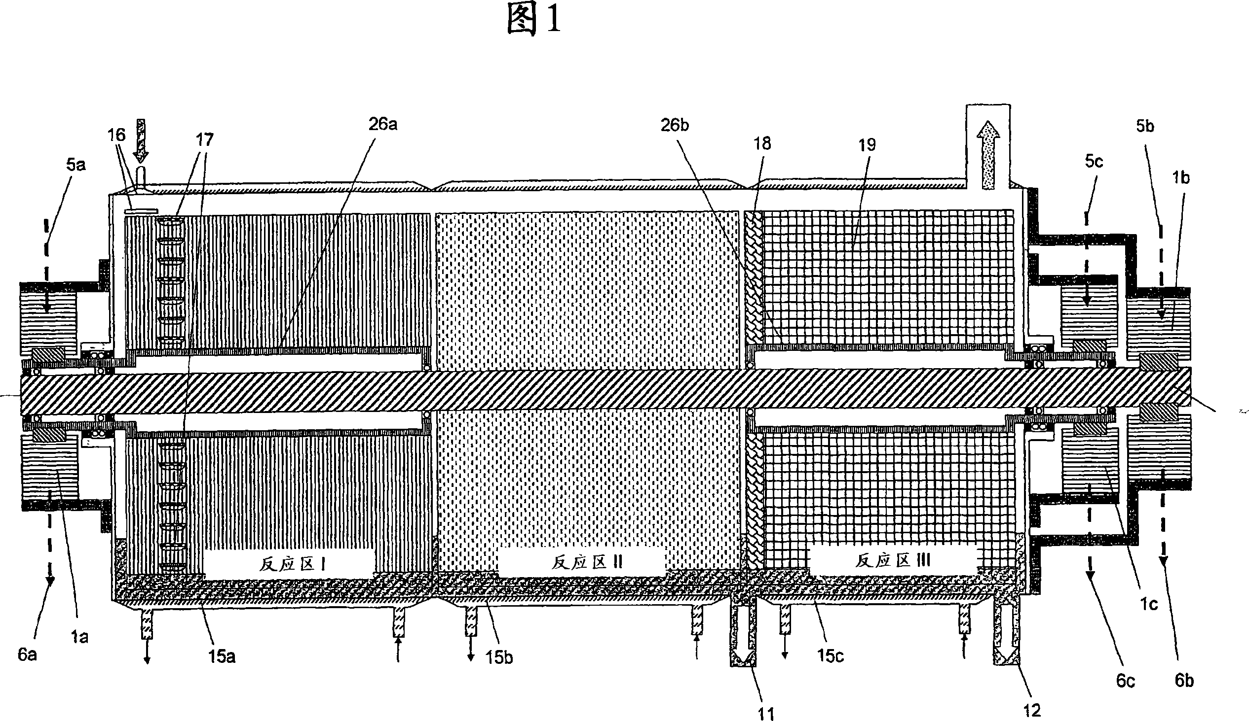
[0047] FIG. 1 shows a reactor with three reaction zones for the continuous degassing of reaction products from carboxylic acids of a multifunctional alcohol. The reactor has three hydraulic drives 1a, 1b and 1c for the three rotors of reaction zones I, II and III. The drive means for each rotor are respectively connected to the hydraulic system via a feed line 5 and a return line 6 . The hydraulic drive is characterized by a low mass, a controllably low rotational speed, an adjustable reaction using the operating parameters of the drive. The rotor of reaction zone II is fastened on a straight main shaft 25 which is supported on the left in the inner bearing of the hollow shaft of the rotor of reaction zone I and on the right in the inner bearing of the rotor of reaction zone III. The rotor of reaction zone I is fastened on a hollow shaft 26a which is supported on the left side on the end face of the reactor and on the right side on the main shaft. The rotor of reaction zone ...


PUM


Abstract

The present invention relates to a plant for the continuous degassing of reaction products from carboxylic or dicarboxylic acids comprising a multifunctional alcohol, which can be used to produce intrinsic viscosities up to 0.9 dl / g. The inlet of the product in the reactor is distributed via a plurality of slit nozzles onto the reaction surface in the inlet part before flowing into the tank and an additional preactivated formation of the necessary reaction surface of the product is achieved by means of the product receiving device. The reactor comprises a plurality of reaction zones, which are driven by separately acting rotors with respective associated hydraulic systems, each hydraulic system being installed outside the reactor. In this case the measured values ​​from the behavior of the hydraulic system are used to control the reaction of the product in order to influence the attainment of predetermined product parameters and qualities. Reactors have one or more individual product discharges depending on the product properties to be achieved.

Description

technical field [0001] The invention relates to a reactor for flowable highly viscous or pasty media according to the features in the preambles of the independent claims. Background technique [0002] DE-OS 10200230 A1 describes a stirring drive for vertical and horizontal reactors, which is designed as a hydraulic motor. The arrangement of the motor is carried out directly in the reactor, wherein the product charged into the reactor serves as the hydraulic medium for the drive. The hydraulic medium is fed to the drive via pipelines, and the drive energy is generated by an external pump station. After the drive power for the stirrer has been transferred, the product is introduced as a reactant into the reactor and leads to a further reaction there. [0003] In this variant, if the drive mechanism arranged in the reactor fails or is damaged, the reaction process must be stopped and repaired by opening to the atmosphere. Furthermore, no control of the process is used in thi...

Claims


Application Information

Patent Timeline
Patent Type & Authority Applications(China)
IPC IPC(8): B01J19/18B01F7/04B01F35/60
CPCB01F15/00207B01F15/00363C08G63/181B01J2219/00213C08G63/785B01F15/005B01J2219/00006B01J2219/00094B01F7/043B01J2219/00202B01J19/18B01F15/00545B01J2219/00168B01J2219/00234B01J2219/00189B01F15/00246B01J2219/182B01F27/703B01F35/213B01F35/2136B01F35/2214B01F35/32015B01F35/32045B01F27/705
Inventor M·施特伦C·舍费尔斯屈佩尔A·希尔珀特
Owner EPC工程与技术有限公司
Learn More