
A retractable spring stop fitting for a seat recliner

A seat recliner and retractable technology, which is applied to vehicle seats, vehicle parts, special positions of vehicles, etc., can solve the problems of large space size, poor synchronization, and unusable springs, etc., to achieve improved locking strength, Simplified structure, direct effect

Active Publication Date: 2016-03-30
YANFENG ANDAOTUO YANTAI SEATING CO LTD
View PDF9 Cites 0 Cited by
  • Summary
  • Abstract
  • Description
  • Claims
  • Application Information

AI Technical Summary

Problems solved by technology

However, the two ends of the spring in this patent are respectively fixed on the first fitting and the eccentric cam, and there is a coil or a conversion profile on the radially outside of the fixed point of the locking element, so the synchronization of the unlocking is poor.
In addition, due to the large space occupied by the spring during the winding process, if two eccentric cams are required to drive multiple locking elements such as four for locking, this spring cannot be applied

Method used


Image

  • A retractable spring stop fitting for a seat recliner
  • A retractable spring stop fitting for a seat recliner
  • A retractable spring stop fitting for a seat recliner

Examples


Embodiment 1

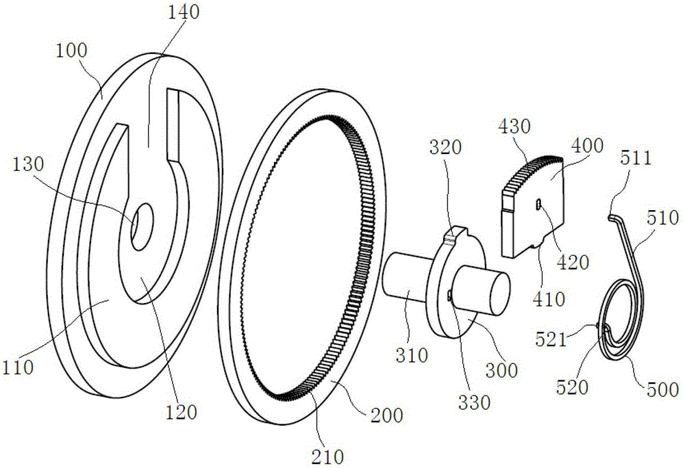
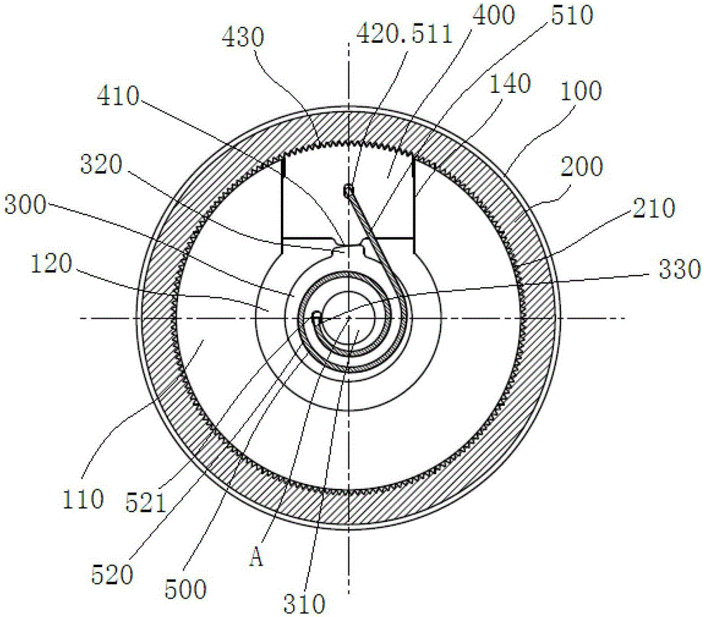
[0053] see figure 1 and figure 2 , a retractable spring stop fitting for a seat recliner is shown in the figure, which includes a main board 100 installed on the seat cushion side and a toothed plate 200 installed on the backrest side. Of course, the main board can also be installed as required 100 is installed on the backrest side, and the tooth plate 200 is installed on the seat cushion side.

[0054] The gear plate 200 has an inner ring gear 210 so that the gear plate 200 is locked on the main board 100 without rotation.

[0055] On the surface of the main board 100 opposite to the side of the tooth plate 200, an annular guide 110 protruding into the ring gear 210 is provided. In the center of the annular guide 110, there is an inner chamber 120 for the rotation of the cam 300. A shaft hole 130 for inserting the inner end of the camshaft 310 is defined in the center of the inner chamber 120 . A channel 140 for the radial movement of the lock plate 400 is provided on the...

Embodiment 2

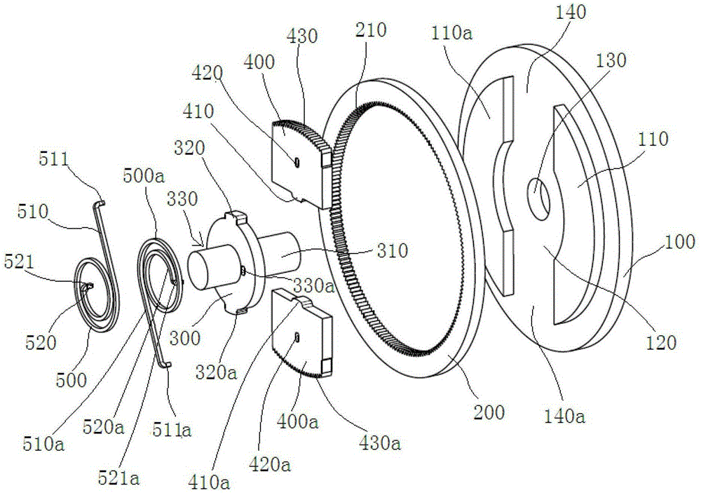
[0062] see image 3 and Figure 4 , a retractable spring stop fitting for a seat recliner is shown in the figure, which includes a main board 100 installed on the seat cushion side and a toothed plate 200 installed on the backrest side. Of course, the main board can also be installed as required 100 is installed on the backrest side, and the tooth plate 200 is installed on the seat cushion side.

[0063] The gear plate 200 has an inner ring gear 210 . On the surface of the main board 100 opposite to the side of the gear plate 200, two guides 110, 110a extending into the inner ring gear 210 are arranged mirror-symmetrically. The cavity 120 is provided with a shaft hole 130 for inserting the inner end of the camshaft 310 in the center of the cavity 120 . Channels 140, 140a for the radial movement of the two locking plates 400, 400a are arranged in front of the two guides 110, 110a, and the channels 140, 140a are distributed at 180°.

[0064] The locking plates 400, 400a are ...

Embodiment 3

[0071] see Figure 5 and Figure 6 , the difference between a retractable spring stop fitting for a seat recliner given in the figure and Embodiment 2 is that the two retractable springs 500, 500a are integrated into one retractable spring 500', which surrounds the The camshaft 310 of the cam 300 is on the outer end, that is, around the axis A of the cam 300 .

[0072] The retractable spring 500' has a straight middle part 520' and two outer ends 511', 512', the outer end 511' extends obliquely upward in a straight line, and the outer end 512' extends obliquely downward in a straight line, The retractable spring 500' is wound by spring steel wire or directly fine punched by spring steel plate. The ends of the outer ends 511', 512' of the retractable spring 500' are bent toward the lock plates 400, 400a to form an outer hook 511a', 512a', and the outer hooks 511a', 512a' are respectively hooked into the lock plate 400 , 400a in holes 420, 420a.

[0073] A groove 311 is prov...


PUM


Abstract

The invention discloses a shrinkage type spring locking accessory for a seat angle regulator. The shrinkage type spring locking accessory for the seat angle regulator comprises a main board installed on a seat cushion side or a backrest side, a toothed plate installed on the backrest side or the seat cushion side and provided with an inner tooth ring, at least one lock plate which interacts with the inner tooth ring of the toothed plate and is guided by the main board, and at least one cam which functions on the toothed plate and can rotate around the axis of the cam, wherein the inner side of the inner tooth ring is arranged inwards along the radial direction of the lock plate, lock teeth meshed with the inner tooth ring are arranged on the periphery of the lock plate, and the cam presses outwards along the radial direction and against the lock plate, so that the lock plate and the inner tooth ring of the toothed plate are enabled to interact. The shrinkage type spring locking accessory for the seat angle regulator further comprises at least one shrinkage type spring, wherein the shrinkage type spring surrounds the axis of the cam, at least one portion of the shrinkage type spring functions on the cam, and furthermore at least one another portion of the shrinkage type spring functions on the lock plate. According to the shrinkage type spring locking accessory for the seat angle regulator, more latch contact points can be achieved, so that not only intensity and interval performance of the locking accessory are improved, but also a feasible layout scheme is provided foe a plurality of locking elements simultaneously.

Description

technical field [0001] The invention relates to the technical field of a seat recliner, in particular to a retractable spring stop fitting for a seat recliner. Background technique [0002] WO00 / 44582A1 discloses a stop fitting for a seat recliner. Two pre-compressed helical springs are arranged on both sides of the eccentric cam and act on the eccentric cam, which in turn acts on the locking element in a radially outward direction. Circumferential movement of the locking element is limited by the first fitting. Radially outside the locking element interacts with the second fitting to lock the stop fitting. In order to unlock the stop fitting, the eccentric cam needs to be rotated against the spring return force under the action of an external force, and at the same time drive the control disc located on the eccentric cam to rotate, thereby pulling the locking element with a convex feature inwards, and finally the locking element and the second Accessories are out of inte...

Claims


Application Information

Patent Timeline
Patent Type & Authority Patents(China)
IPC IPC(8): B60N2/235
Inventor 张力康海华付小广唐臻毅
Owner YANFENG ANDAOTUO YANTAI SEATING CO LTD
Learn More