Method and device for making consistence of anvil-roller and knife roller linear velocity

A technology of line speed and anvil roller, which is applied in the direction of transportation and packaging, packaging, rigid/semi-rigid container manufacturing, etc., and can solve the problems of irreconcilable purchase cost and use cost of die-cutting machines, high cost, etc.

Inactive Publication Date: 2011-06-22
北京万源多贝克包装印刷机械有限公司
View PDF0 Cites 0 Cited by
  • Summary
  • Abstract
  • Description
  • Claims
  • Application Information

AI Technical Summary

Problems solved by technology

The smoother the speed change curve of the transmission system and the smaller the steps, the higher the cost, which has become an irreconcilable contradiction between the purchase cost and the use cost of the die-cutting machine

Method used


Image

  • Method and device for making consistence of anvil-roller and knife roller linear velocity
  • Method and device for making consistence of anvil-roller and knife roller linear velocity
  • Method and device for making consistence of anvil-roller and knife roller linear velocity

Examples


Embodiment 1

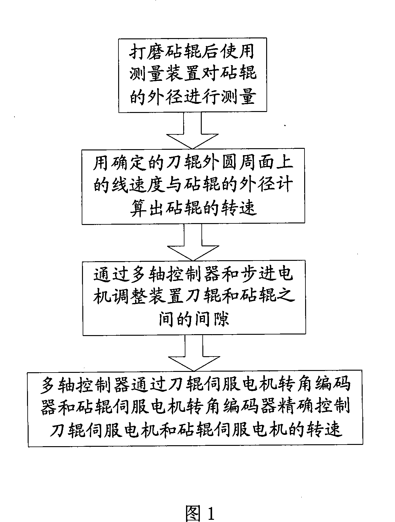
[0016] This embodiment is a method for making the anvil roll and knife roll linear speed consistent, and its process is shown in figure 1 The schematic block diagram. The devices used in this method are figure 2 As shown, it includes: knife roll 1, knife roll servo motor 6 driving the knife roll, knife roll servo motor angle encoder 8, anvil roll 2, anvil roll servo motor 5 driving the anvil roll, anvil roll servo motor angle encoder 7 3. The device for measuring the diameter of the anvil roll 3, the stepper motor adjustment device 10 for adjusting the gap between the anvil roll and the knife roll, the multi-axis controller 9, the steps of the method:

[0017] After grinding the anvil roll, use a measuring device to measure the outer diameter of the anvil roll. After grinding the anvil roll, it can be measured manually, using traditional measuring tools, such as micrometers, calipers or calipers, etc., as long as the accuracy meets the requirements. Input the measured data...

Embodiment 2

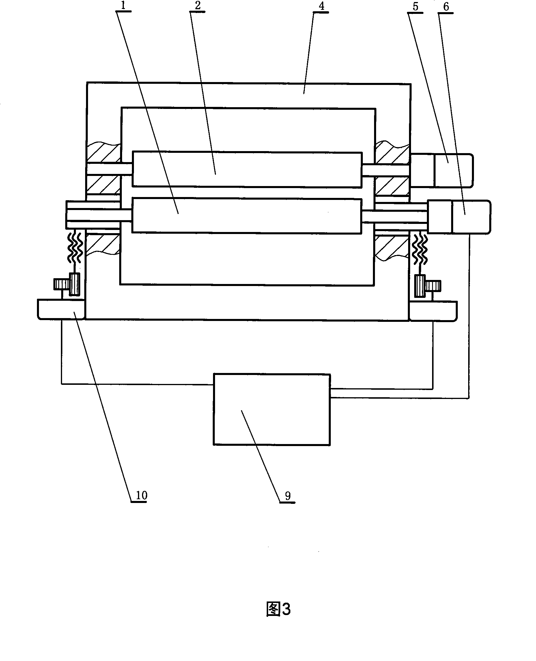
[0022] This embodiment is a device that makes the linear speeds of the anvil roll and the knife roll consistent, and is a device for realizing the method described in Embodiment 1. The device is as follows: image 3 shown.

[0023] The present embodiment includes a frame 4 as the whole machine skeleton.

[0024] The anvil roller 2 installed on the frame, the surface of the anvil roller is flexible rubber or plastic, has good wear resistance and elasticity, and the surface friction force is relatively large, which can drive the cardboard to move forward.

[0025] Below the anvil roll, the knife roll 1 is installed on the frame through a stepping motor adjustment device 10 for adjusting the gap between the knife roll and the anvil roll. The knife roller is the main device for the die-cutting machine to make creases on the cardboard. By cooperating with the anvil roller, on the one hand, it drives the cardboard to move forward, and at the same time, it uses the protruding ribs o...

Embodiment 3

[0030] This embodiment is an improvement of Embodiment 2, and the structure is as follows Figure 4shown. One end of the shaft end of the anvil roller servo motor 5 that is not connected to the speed reducer is connected with an anvil roller servo motor rotary angle encoder 7 for measuring the rotational angle of the anvil roller servo motor. One end of the shaft end of the cutter roller servo motor 6 that is not connected to the reducer is connected with a cutter roller servo motor rotation angle encoder 8 for measuring the rotation angle of the cutter roller servo motor. An anvil roller servo motor rotation angle encoder, a knife roller servo motor rotation angle encoder are electrically connected to the multi-axis controller.


PUM


Abstract

The present invention relates to a method and a device which enable an anvil roller and a knife roll to have the same linear velocity, and a method and a device used in a die cutting machine; wherein, the die cutting machine presses and cuts out prints on the cardboard manufacturing carton box so as to be folded. The invention comprises a machine frame and the anvil arranged on the machine frame as well as the knife roll arranged on the machine frame through a steeping motor adjusting device, which is arranged at the seam position between the adjusting knife roll at the bottom of the anvil and the anvil. The anvil is driven by the anvil servo electric motor driven by a speed reducer. The knife roll is driven by the knife roll servo electric motor which is driven by the speed reducer. The anvil servo electric motor and the knife roll servo electric motor as well as the stepping electric motor of the steeping motor adjusting device are electrically connected with a multi axle controller. The invention adopts two servo electric motors to respectively drive the anvil and the knife roll, achieves the consistence of the linear velocity of the anvil and the knife roll, and solves the problem that the complex mechanical structure is not able to solve by the means of electric control; furthermore, the invention achieves the highly accurate synchronous of the linear velocity for the anvil and the knife roll through the feedback of an encoder.

Description

technical field [0001] The invention relates to a method and a device for making the linear speeds of an anvil roller and a knife roller consistent, a method and a device applied to a machine for manufacturing packaging cartons, and a method and device for cutting lines or pressing out marks on a cardboard for manufacturing cartons. Method and apparatus for use on a die-cutter for folding. Background technique [0002] Known die-cutters usually have two calender rolls, an anvil roll made of rubber and a knife roll with raised ribs. The two rolling rollers go up and down, leaving a gap in the middle to allow the cardboard to pass through. The surface of the rolling roller is soft and has a large friction force, which mainly drives the movement of the cardboard and serves as an anvil pad for the edge of the knife. The ribs on the knife roller are the so-called "knife", which is the main tool for rolling out the creases on the cardboard. Ideally, the linear speeds of the out...

Claims


Application Information

Patent Timeline
Patent Type & Authority Patents(China)
IPC IPC(8): B31B1/25B31B50/25
Inventor 李晓鸣窦雪原王梅珍成永良
Owner 北京万源多贝克包装印刷机械有限公司
Why Eureka
Try Eureka