
An evaporation cavity heat radiator

A radiator and steam chamber technology, which is applied in the direction of instruments, instrument cooling, instrument parts, etc., can solve problems such as the inability of heat energy to dissipate rapidly, the infiltration of heat dissipation liquid, and the inability to accommodate too much heat dissipation liquid in the capillary space.

Inactive Publication Date: 2010-06-02
SUZHOU JIAOZI INFORMATION TECH CO LTD
View PDF3 Cites 0 Cited by
  • Summary
  • Abstract
  • Description
  • Claims
  • Application Information

AI Technical Summary

Problems solved by technology

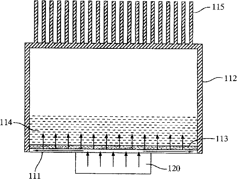
[0004] However, the previous technology has the following unavoidable disadvantages, that is, the thickness of the heat conduction powder easily affects the heat dissipation effect of the heat dissipation liquid, which includes:
[0005] 1. If the thickness of the heat-conducting powder is too thin, the capillary space formed will be too scarce to accommodate too much heat dissipation liquid. This will cause when the heat dissipation liquid absorbs heat and forms a gaseous state, other liquid heat dissipation liquids will It is impossible to quickly fill the vacancy in the capillary space through the action of capillary phenomenon, which will hinder the conduction of heat energy and cause the heat energy to fail to dissipate quickly
[0006] 2. If the heat-conducting powder is spread too thickly, the heat-conducting powder will become too dense after sintering, and the cooling liquid cannot penetrate into the capillary space at the bottom of the heat-conducting powder, so that the heat energy cannot be conducted to the cooling liquid, resulting in the inability to dissipate heat through The liquid dissipates heat

Method used


Image

  • An evaporation cavity heat radiator
  • An evaporation cavity heat radiator
  • An evaporation cavity heat radiator

Examples


Embodiment Construction

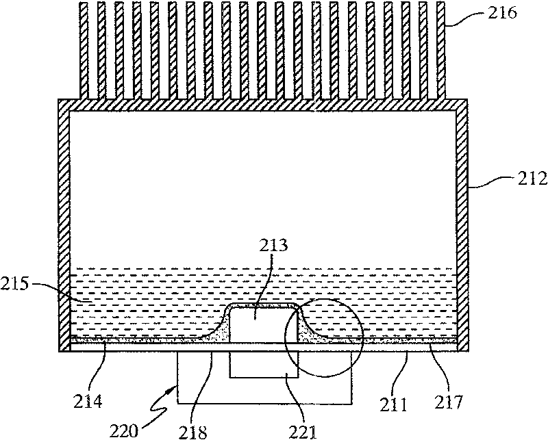
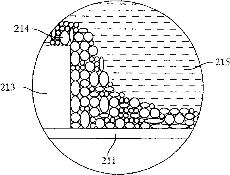
[0042] Please refer to Figure 2A and Figure 2B , which is a schematic structural diagram of the radiator and a detailed diagram of some components in the first embodiment of the present invention, which mainly includes a heat dissipation base 211, a cover body 212, a raised portion 213, a heat conduction powder 214, a heat dissipation liquid 215 and a plurality of fins 216, while the outside has a heating element 220, and the heating element 220 has a heating portion 221 that can generate heat energy.

[0043] Wherein, the heat dissipating base 211 has a base veneer 218 for bonding the heating element 220 and an inner surface 217 facing the accommodating space, and the inner surface 217 is provided with a protrusion 213 corresponding to the base veneer 218 . Moreover, when the heat dissipation base 211 is engaged with the cover body 212 , an airtight accommodating space is formed therebetween for accommodating the heat dissipation liquid 215 . And the heat conduction powde...


PUM


Abstract

The invention relates to a steam housing radiator which is jointed on a heating element and disperses the heat energy generated by the heating element through the liquid phase change. The steam housing radiator is provided with a covered body, a radiating base seat jointed on the heating element and heat conducting powder; wherein, the covered body is jointed on the radiating base seat and a closed holding space is formed between the covered body and the radiating base seat so as to hold the radiating liquid that radiates by liquid phase change. The inner surface of the radiating base seat facing to the holding space is provided with a convex part corresponding to the heating element and the heat conducting power is arranged on the surface to form a capillary space. Simultaneously as the heat conducting power deposited in the circumference of the convex part is more than the heat conducting power arranged in other areas, more capillary spaces are provided so as to make use of the capillary phenomenon to transfer heat more effectively and improve the radiating effect.

Description

technical field [0001] The invention relates to a steam cavity radiator, in particular to a steam cavity radiator in which capillary space is added around a heat source in the cavity to effectively utilize capillary phenomena to improve heat dissipation efficiency. Background technique [0002] Please refer to figure 1 , which is a schematic structural diagram of a general steam chamber radiator. According to the current steam cavity radiators on the market, there must be a cavity 112 to accommodate the heat dissipation liquid 114 that dissipates heat energy through the change of liquid and gas phases, and the side of the cavity 112 corresponding to the heating element 120 is usually It is a plane, evenly spread the heat conduction powder 113, and sinter it on this plane. The sintered heat-conducting powder 113 forms a plurality of capillary spaces for accommodating the cooling liquid 114 . In other words, the cooling liquid 114 infiltrates between the heat-conducting powd...

Claims


Application Information

Patent Timeline
Patent Type & Authority Patents(China)
IPC IPC(8): G12B15/00H05K7/20
Inventor 陈文华林茂青
Owner SUZHOU JIAOZI INFORMATION TECH CO LTD
Learn More