Double-pendulum internal-combustion engine
A dual-swing rod, internal combustion engine technology, applied in mechanical equipment, machines/engines, etc., can solve the problem of low energy conversion efficiency, and achieve the effects of being beneficial to environmental protection, reducing fuel consumption, and reducing exhaust emissions
Inactive Publication Date: 2010-09-08
闫官清
View PDF0 Cites 0 Cited by
- Summary
- Abstract
- Description
- Claims
- Application Information
AI Technical Summary
Problems solved by technology
It can be seen that the advantages of modern crank-connecting rod internal combustion engines are simple structure and reliable operation, but the disadvantage is that the energy conversion efficiency is not high due to structural reasons
Method used
View moreImage
Smart ImageViewing Examples


Examples
Embodiment 1
Embodiment 2
Login to View More PUM
 Abstract
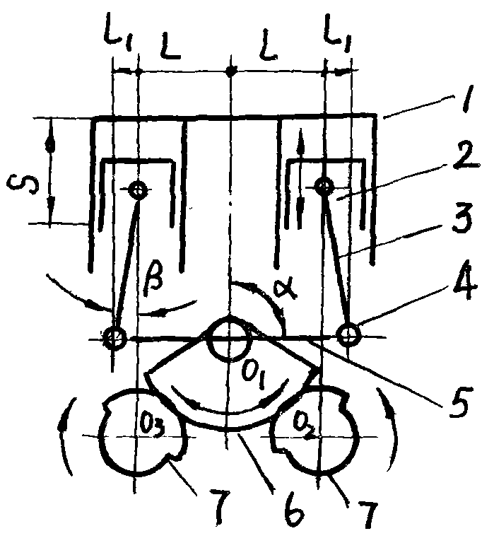
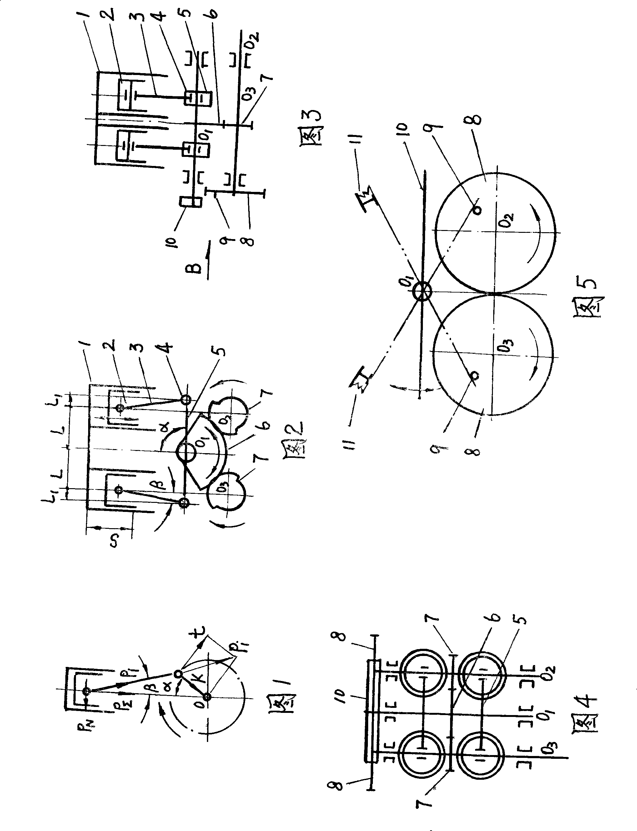
A gas engine with double swing stems mainly comprises a cylinder, a piston group, a connecting bar, and a double-swing stem. The engine is characterized in that a spigot shaft O1 is arranged in the center of the stander. The rigid double-swing stem, a sector center gear, a control endergonic pole are fixed in the axis. The two ends of the double-swing stem are connected with the lower end of a piston rod respectively. The sector center gear is meshed with two semicircle gears on an output shaft O2, and a gear shaft O3 and a pair of gear idles are used to output power. The control endergonic pole can control the upper and lower dead center and the swerve motion of the piston with the output shaft O2, the gear shaft O3, a control cam on the gear idles and a power storage retainer on the stander; and the present invention can use the to-and-fro inertia force of the piston, etc. The output of the energy can also be realized in the way of hydraulic pressure or gas pressure. The engine can improve 30 to 35 percent of the output force of the gas engine or reduce 20 to 25 percent of the oil consumption of the gas engine, reduce the discharge amount of the exhaust amount, increase the use life, and prolong the maintenance period; the application domain is the same as the bent axle engine.
Description
【Technical field】 The invention relates to an internal combustion engine, in particular to a double swing rod internal combustion engine. 【Background technique】 The known way of energy conversion and output of the existing internal combustion engine is: the gas expansion pressure generated by the combustion of fuel in the cylinder acts on the piston, and after adding the reciprocating inertial force of the piston group, the resultant force P ∑ It is transmitted to the crank pin through the connecting rod, and then the torque is obtained by the tangential component t on the crank pin to push the crankshaft to rotate and output its energy. The numerical expression of its tangential component force t value is t=P ∑ [sin(α+β) / cosβ], due to the kinematics characteristics of the crank-link mechanism, when the piston is at the upper and lower "dead points", the crank angle α and the connecting rod swing angle β are both zero. It can be seen that the t value is between zero and P ...
Claims
Login to View More Application Information
Patent Timeline
 Patent Type & Authority Patents(China)
IPC IPC(8): F02B75/20F02B75/32
Inventor 闫官清
Owner 闫官清
Features
- R&D
- Intellectual Property
- Life Sciences
- Materials
- Tech Scout
- Unparalleled Data Quality
- Higher Quality Content
- 60% Fewer Hallucinations
Learn More Browse by: Latest US Patents, China's latest patents, Technical Efficacy Thesaurus, Application Domain, Technology Topic, Popular Technical Reports.
© 2025 PatSnap. All rights reserved.Legal|Privacy policy|Modern Slavery Act Transparency Statement|Sitemap|About US| Contact US: help@patsnap.com