Article having a birefringent surface for use as a blur filter
A fuzzy filter, birefringence technology, applied in instruments, polarizing components, optics, etc., can solve problems that are difficult to handle, easy to break, and cannot be loaded into mobile phones or personal digital assistants with digital cameras
- Summary
- Abstract
- Description
- Claims
- Application Information
AI Technical Summary
Problems solved by technology
Method used
Image
Examples
Embodiment 1
[0135] Example 1 - Preparation of Oriented Microstructured Films
[0136] Polyethylene terephthalate (PET) with an intrinsic viscosity (I.V.) of 0.74 (available from Eastman Chemical Company, Kingsport, Tennessee, USA) was used in this example.
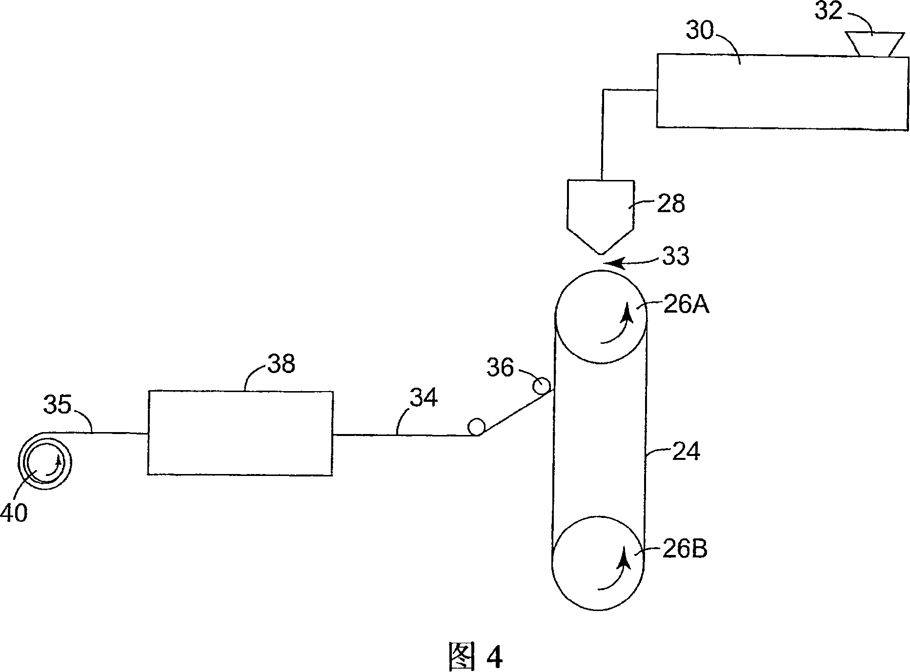
[0137] The PET pellets were dried to remove residual moisture and loaded into the extruder hopper under a nitrogen purge. PET was extruded in the extruder and the melter assembly connected thereto up to a temperature profile of 232°C to 282°C at the die (where the die was set at 282°C). The pressure of the melter assembly is continuously monitored and averaged at the last of a plurality of monitoring locations located along the melter assembly, and the die is then brought in close proximity to the tool on which the polymer film will be formed (the tool Simultaneously, the opposite first surface of the film is structured).
[0138] The tool was a structured ribbon of nickel alloy of unknown composition (manufactured by 3M Company) wi...
Embodiment 2
[0145] Embodiment 2--double-layer microstructured fuzzy filter
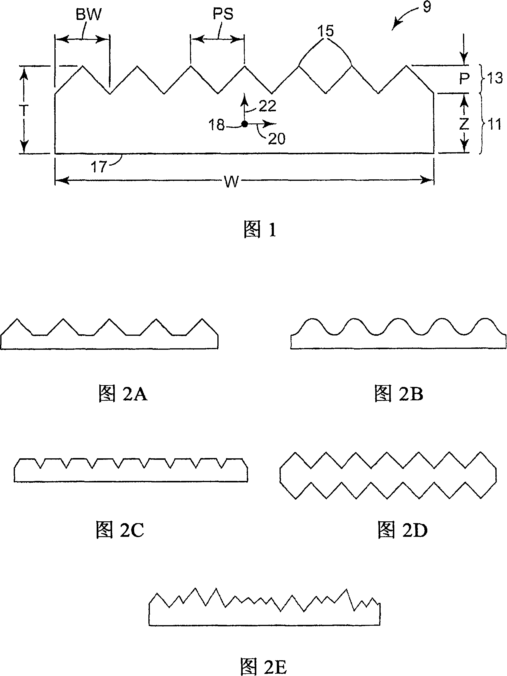
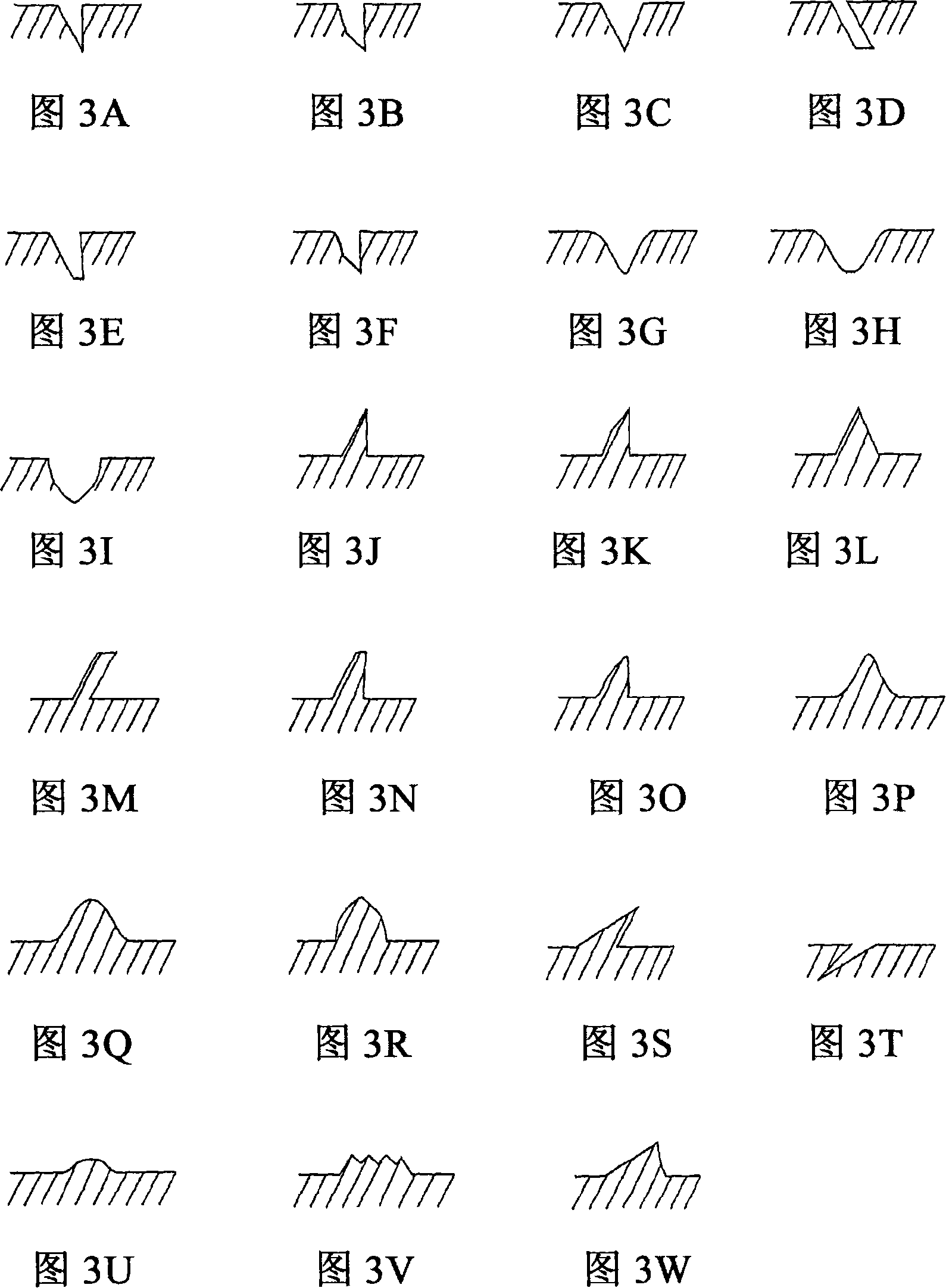
[0146] To create the microstructure in film 1, the unoriented (amorphous state) cast PEN material was directly cut into the following dimensions by diamond turning on a lathe before stretching: pitch of prisms on one surface of the film is about 89 microns, the apex angle is about 86°, one side of its cross-sectional triangle is inclined at 4° with respect to the horizontal line of the film substrate, and the side opposite to the side is inclined at 0° with respect to the vertical line, and Its depth is 6.5 microns. The obtained film was uniaxially stretched under the condition that the stretch ratio was 3, and the prismatic replication surface had the following dimensions and characteristics after stretching: the pitch was 49.8 microns, the apex angle was about 86°, and its cross-section was triangular. One side was inclined at 4° with respect to the horizontal of the film substrate and the opposite side was in...
Embodiment 3
[0152] Example 3 - two-dimensional (2D) controllable beam splitting
[0153] Before stretching, the film sample had a prismatic surface structure with an apex angle of about 90°, one side of its cross-sectional triangle inclined at 30° with respect to the horizontal line of the film substrate, and The opposite side is inclined at 30° relative to the vertical, and the prism pitch is 25 microns.
[0154] The film sample is uniaxially stretched under the condition that the uniaxial stretching ratio is 6, and the prismatic replication surface obtained after stretching has the following dimensions and characteristics: the pitch is 14.1 microns, and the apex angle is about 92°, which One side of the cross-sectional triangle was inclined at 28° relative to the horizontal of the film substrate and the opposite side was inclined at 30° relative to vertical, and had a depth of about 3.6 microns. Refractive index was measured on the back side of the stretched film using a Metricon prism...
PUM
| Property | Measurement | Unit |
|---|---|---|
| Thickness | aaaaa | aaaaa |
| Thickness | aaaaa | aaaaa |
Abstract
Description
Claims
Application Information
 - R&D Engineer
- R&D Manager
- IP Professional
- Industry Leading Data Capabilities
- Powerful AI technology
- Patent DNA Extraction
Browse by: Latest US Patents, China's latest patents, Technical Efficacy Thesaurus, Application Domain, Technology Topic, Popular Technical Reports.
© 2024 PatSnap. All rights reserved.Legal|Privacy policy|Modern Slavery Act Transparency Statement|Sitemap|About US| Contact US: help@patsnap.com


