


Quick Research
Generate reliable direction feasibility study reports for your R&D in just a few steps.

Technical Q&A
Discover and master advanced knowledge NOW. Basics, ideas, possibilities, all at once.

Find Solutions
As an expert in R&D theories, this can generate solutions to your technical problems instantly.

Evaluate Feasibility
Analyze your overall solution with one click, know your potential R&D risks in advance.

Monitor Landscape
Get weekly tech updates, stay abreast of the latest tech innovations and key insights.
Secured fixing screw
A technology of anti-loosening and screw shank, which is applied in the direction of bolts, nuts, threaded fasteners, etc., and can solve problems such as high cost
- Summary
- Abstract
- Description
- Claims
- Application Information
AI Technical Summary
Problems solved by technology
Method used
Image

Examples
Embodiment Construction
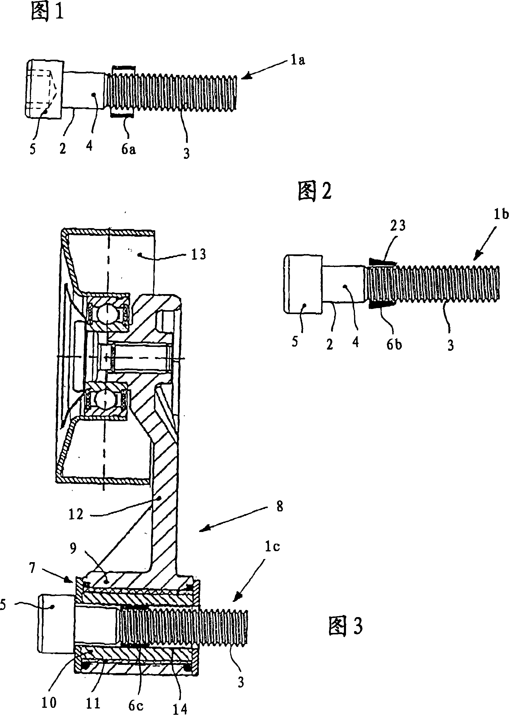
[0017] FIG. 1 shows a hexagon socket head cap screw, which can be used as a connecting screw 1a for a structural part of a traction tool drive. A screw shank 2 has a threaded section 3 and a further smooth-surfaced section 4 which extends between the screw head 5 and the threaded section 3 . The threaded section 3 is provided with a cylindrical sleeve 6a, which serves to secure the connecting screw 1a, on this threaded section, for example, a sleeve is inserted into the receiving hole for the connecting screw 1a and thus locally narrows the receiving diameter. Due to the narrowed diameter and the elastic sleeve 6a, the connecting screw 1a is fastened in the receiving opening in a loose-fixed manner.
[0018] FIG. 2 shows the connection screw 1b in combination with a sleeve 6b shrink-fitted using thermal technology. This type of fixing ensures that the sleeve 6b is immovably fixed on the threaded section 3 of the connecting screw 1b. In order to allow the connecting screw 1b ...
PUM
 Abstract
Description
Claims
Application Information
 - R&D Engineer
- R&D Manager
- IP Professional
- Industry Leading Data Capabilities
- Powerful AI technology
- Patent DNA Extraction
Browse by: Latest US Patents, China's latest patents, Technical Efficacy Thesaurus, Application Domain, Technology Topic, Popular Technical Reports.
© 2024 PatSnap. All rights reserved.Legal|Privacy policy|Modern Slavery Act Transparency Statement|Sitemap|About US| Contact US: help@patsnap.com