Fuel cell system

A fuel cell system and fuel cell technology, applied in the direction of fuel cells, fuel cell additives, fuel cell grouping, etc., can solve the problems of large surface area and low thermal efficiency of the shell 1, and achieve reduced heat radiation, uniform temperature, and reduced heat dissipation. radiation effect

Inactive Publication Date: 2008-01-16
HONDA MOTOR CO LTD
View PDF1 Cites 0 Cited by
  • Summary
  • Abstract
  • Description
  • Claims
  • Application Information

AI Technical Summary

Problems solved by technology

Shell 1 has a large surface area, resulting in low thermal efficiency

Method used


Image

  • Fuel cell system
  • Fuel cell system
  • Fuel cell system

Examples


Embodiment Construction

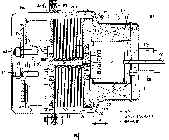
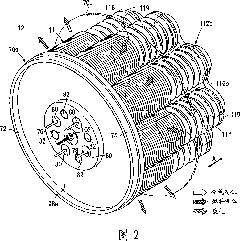
[0036] FIG. 1 is a partial sectional view showing a fuel cell system 10 according to a first embodiment of the present invention. FIG. 2 is a perspective view schematically showing the fuel cell stack 12 of the fuel cell system 10 . The fuel cell stack 12 is formed by stacking a plurality of fuel cells 11 in the direction indicated by arrow A. As shown in FIG.

[0037] The fuel cell system 10 is used in a variety of applications, including stationary and mobile applications. For example, the fuel cell system 10 is mounted on a vehicle. As shown in FIG. 1 , the fuel cell system 10 includes a fuel cell stack 12 , a heat exchanger 14 , a reformer 16 and a housing 18 . Heat exchanger 14 heats the oxygen-containing gas before it is supplied to fuel cell stack 12 . The reformer 16 reforms fuel to produce fuel gas. The fuel cell stack 12 , heat exchanger 14 and reformer 16 are arranged in a housing 18 .

[0038] In the housing 18, a fluid unit 19 comprising at least a heat excha...


PUM


Abstract

A fuel cell system (10) includes a fuel cell stack (12), a heat exchanger (14), a reformer (16), and a casing (18) containing the fuel cell stack (12), the heat exchanger (14), and the reformer (16). A chamber unit (98) is formed at an end plate (70a) of the fuel cell stack (12). The air heated by the heat exchanger (14) temporarily fills the chamber unit (98). The heat exchanger (14) and the reformer (16) are directly connected to the chamber unit (98).

Description

technical field [0001] The present invention relates to a fuel cell system, which includes a fuel cell stack, a heat exchanger and a reformer arranged in a case. Background technique [0002] Typically, solid oxide fuel cells (SOFCs) employ electrolytes of ion-conducting solid oxides such as stabilized zirconia. An electrolyte is interposed between an anode and a cathode to form an electrolyte electrode assembly (unit cell). The electrolyte electrode assembly is interposed between separators (bipolar plates). In use, a predetermined number of unit cells and separators are stacked together to form a fuel cell stack. [0003] In a fuel cell, an oxygen-containing gas or air is supplied to the cathode. Oxygen in the oxygen-containing gas is ionized at the interface between the cathode and the electrolyte, and oxygen ions (O 2- ) moves through the electrolyte toward the anode. Fuel gas such as hydrogen-containing gas or CO is supplied to the anode. At the anode, oxygen ions...

Claims


Application Information

Patent Timeline
Patent Type & Authority Applications(China)
IPC IPC(8): H01M8/02H01M8/04H01M8/06H01M8/24
CPCH01M8/0625H01M8/04007Y02E60/521H01M8/1002H01M8/04014H01M8/04201H01M8/2475H01M8/248H01M8/2428H01M8/2432H01M8/2483Y02E60/50H01M8/04H01M8/06H01M8/24
Inventor 角田正本间弘树小川哲矢
Owner HONDA MOTOR CO LTD
Why Eureka
Try Eureka