
Biomass fuel boiler

A biomass fuel and boiler technology, applied in the boiler field, can solve the problems of reduced heat exchange efficiency, long boiler start-up time, large water content, etc., to ensure heat exchange efficiency and silo safety, shorten start-up time, and long service life Effect

Active Publication Date: 2008-01-16
CHINA WESTERN POWER INDAL
View PDF2 Cites 26 Cited by
  • Summary
  • Abstract
  • Description
  • Claims
  • Application Information

AI Technical Summary

Problems solved by technology

[0002] According to statistics, as of the end of 2004, the total installed capacity of biomass fuel power generation represented by straw in the world has reached 39 million kilowatts, which can replace 70 million tons of standard coal, which is the sum of wind power, photovoltaic, geothermal and other renewable energy power generation. Traditional coal-fired boilers include drum, furnace, feed pipe, first flue, second flue, tail shaft flue, primary air chamber, secondary air supply device, water-cooled vibrating grate, superheater, province Coal burners, air preheaters, blowers, etc., cannot be applied to biomass fuels, because biomass fuels have a small specific gravity and large volume, and full combustion cannot be achieved when burning on the upper layer of the grate, and the furnace is under positive pressure, and the fuel entering the furnace It may be blown into the silo above the feed pipe through the feed pipe, causing a fire; secondly, some biomass fuels have a high tar content, and the smoke generated is relatively viscous, which is easy to burn in high-temperature pipes (superheaters, etc.) ), corrodes the pipes and reduces the heat transfer efficiency, and the viscous flue gas is easy to form a net in the narrow flue, which affects the normal flow of the flue gas and reduces the heat transfer efficiency of the boiler; moreover, the biomass fuel The calorific value is low, the moisture is large, the fire is difficult, and the boiler startup time is long; later, people have made some improvements to the boiler according to the characteristics of biomass fuel, such as the patent number: ZL03150475 and the application number: 200610029424. Biomass fuel boilers, the former is equipped with a feeding hinge in the feeding pipe, and an upper arch and a sectioned air nozzle connected to the main air duct are added in the furnace, which is helpful to the ignition and burnout of the biomass fuel, but its combustion The method is still layer combustion, which does not achieve the best combustion; the latter adds a secondary air duct connected to the blower below the feed port, and its combustion method is layer combustion and a certain degree of suspension combustion, but it is still dominated by layer combustion , and the secondary air is cold air at normal temperature, the temperature in the furnace fluctuates greatly, and sufficient combustion cannot be achieved. The most important thing is that neither of them solves the corrosion of the tube by the viscous flue gas and the influence on the heat exchange efficiency and silo safety issues

Method used


Image

  • Biomass fuel boiler
  • Biomass fuel boiler
  • Biomass fuel boiler

Examples


Embodiment 1

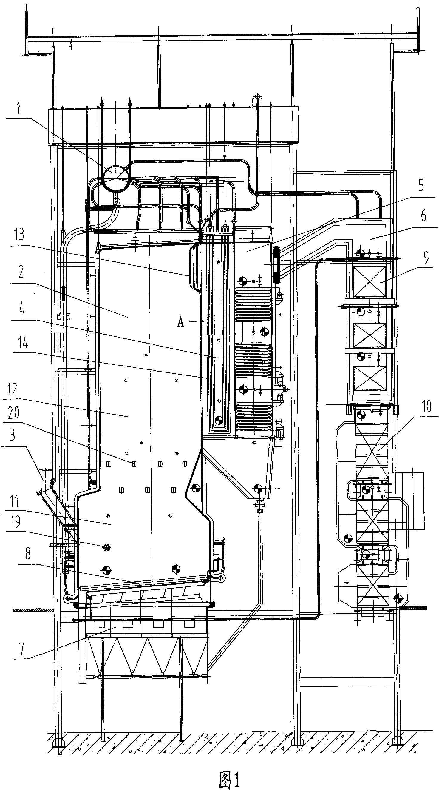
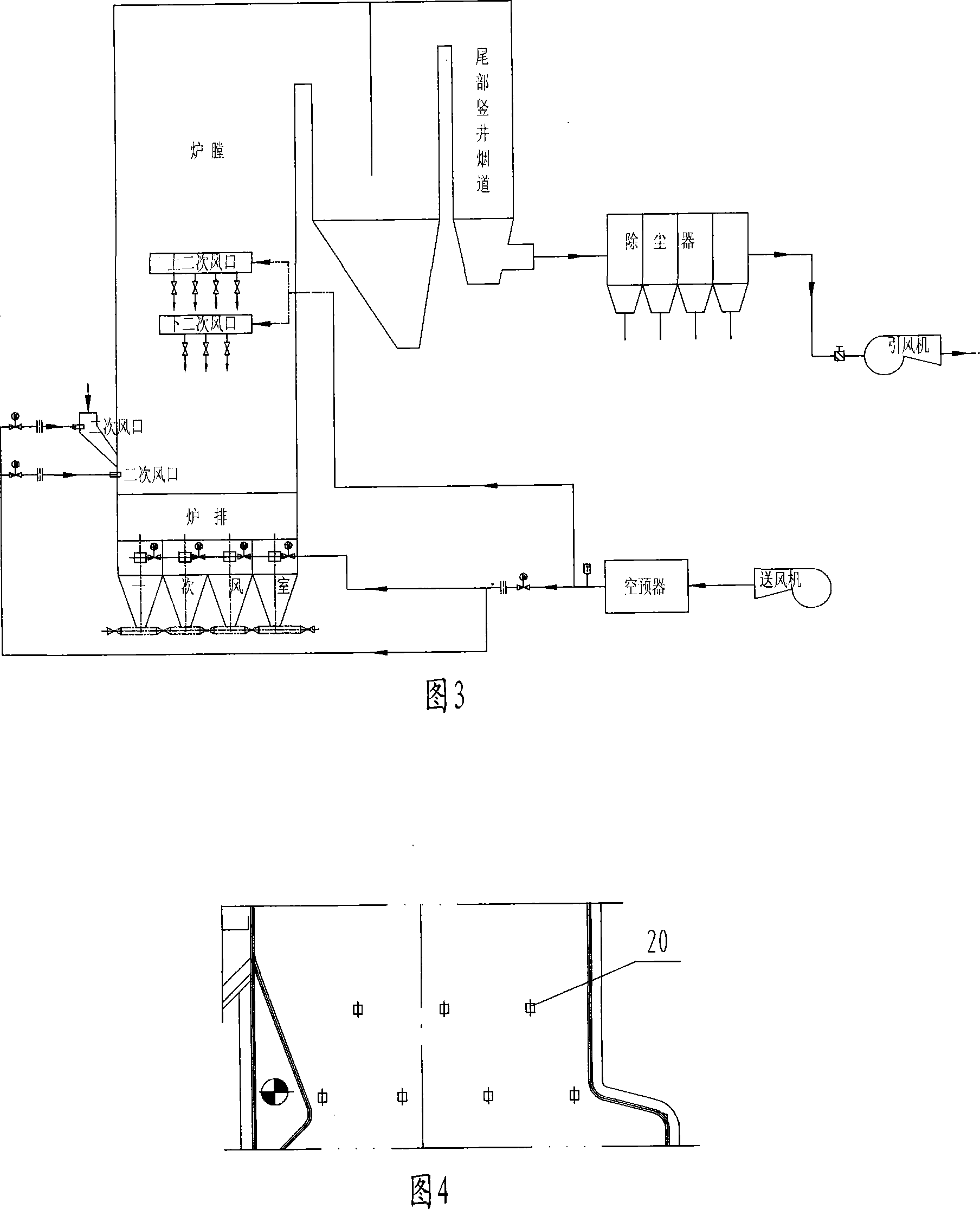
[0023] The biomass fuel boiler is suitable for yellow straw biomass with high tar content. Shaft flue 6, primary air chamber 7, secondary air supply device, water-cooled vibrating grate 8, economizer 9, air preheater 10, blower (not shown), etc., wherein the furnace 2, the first flue 4 and the second flue 5 are all provided with a water-cooled wall and a header; as shown in Figure 3, the primary air chamber is connected with the hot air passage of the air preheater through the air pipe; The secondary tuyeres in the furnace below the material pipe, and several secondary tuyeres arranged on the left and right sides of the furnace, (as shown in Figure 1 and Figure 4, the secondary tuyeres 20 are arranged in a staggered manner), all the secondary tuyeres are It is connected with the hot air passage of the air preheater, and there are adjusting baffles in each air outlet of the primary air chamber and all secondary air outlets, and the tail shaft flue is also connected with the dus...

Embodiment 2

[0026] This biomass fuel boiler is suitable for gray straw biomass with low tar content. As shown in Figure 2, the difference between it and Embodiment 1 is that the rear panel superheater 21 in front of the slag tube bundle 13 replaces the first one in the figure. A panel superheater 14 in the flue 4, because the tar content of the gray straw is low, it is not easy to coke even at high temperatures, and the pipes will not be corroded, thereby ensuring heat exchange efficiency.


PUM


Abstract

The invention discloses a biomass fuel boiler based on the original coal burning boiler. A primary air chamber, secondary air ports respectively equipped in a feed pipe and in a furnace cavity below the feed pipe, and a plurality of air ports equipped at the left and right sides of the furnace cavity and staggeredly arranged are connected with an air preheater, and a regulating baffle is respectively provided in each air ports. The invention realizes complete combustion of biomass fuel with suspension combustion as main combustion manner and grate firing as auxiliary combustion manner. As an improvement, the cross-sectional area of the combustion zone in the furnace cavity is larger than the burnout zone; a dregs condensing pipe equipped with a cooling water passage is provided at the inlet port of a first smoke flue; superheaters are disposed at different positions of the boiler in accordance with the type of biomass fuel; a vertical shaft smoke flue at tail portion is sequentially connected with a dust remover and an induced fan; and an adjacent furnace heating device is respectively equipped in the furnace cavity and the lower header tanks of the water-cooled wall of the first and second smoke flues. The invention can prevent high temperature corrosion, assure heat exchange efficiency and storage bin safety, shorten starting time, and prolong service life.

Description

technical field [0001] The invention relates to a boiler using biomass such as straw as fuel. Background technique [0002] According to statistics, as of the end of 2004, the total installed capacity of biomass fuel power generation represented by straw in the world has reached 39 million kilowatts, which can replace 70 million tons of standard coal, which is the sum of wind power, photovoltaic, geothermal and other renewable energy power generation. Traditional coal-fired boilers include drum, furnace, feed pipe, first flue, second flue, tail shaft flue, primary air chamber, secondary air supply device, water-cooled vibrating grate, superheater, province Coal burners, air preheaters, blowers, etc., cannot be applied to biomass fuels, because biomass fuels have a small specific gravity and large volume, and full combustion cannot be achieved when burning on the upper layer of the grate, and the furnace is under positive pressure, and the fuel entering the furnace It may be...

Claims


Application Information

Patent Timeline
IPC IPC(8): F24H1/22F24H9/18
CPCY02E20/34
Inventor 万思本蔡文钢陈金火
Owner CHINA WESTERN POWER INDAL
Learn More