
Steel-self dense concrete built-up construction reinforcing means

A self-compacting concrete and composite structure technology, which is applied in building construction, building maintenance, construction, etc., can solve the problems that the quality of concrete cannot be guaranteed, and the concrete cannot be compacted by vibration, etc., and achieve good reinforcement effect, outstanding reinforcement effect, and seismic performance Good results

Inactive Publication Date: 2008-01-02
CENT SOUTH UNIV
View PDF0 Cites 22 Cited by
  • Summary
  • Abstract
  • Description
  • Claims
  • Application Information

AI Technical Summary

Problems solved by technology

[0004] However, when the steel-concrete composite structure is used for reinforcement, the gap between the formwork and the original member is small, especially when the reinforced member is a heterogeneous member, such as ordinary concrete, there is a problem that the concrete cannot be vibrated and compacted, and the quality of the concrete cannot be guaranteed. Technical bottlenecks limit the practical application of steel-concrete composite structure reinforcement technology, but with the emergence of self-compacting concrete, this technical bottleneck has been overcome, making steel-concrete composite structure reinforcement technology possible

Method used


Image

  • Steel-self dense concrete built-up construction reinforcing means
  • Steel-self dense concrete built-up construction reinforcing means
  • Steel-self dense concrete built-up construction reinforcing means

Examples


Embodiment 1

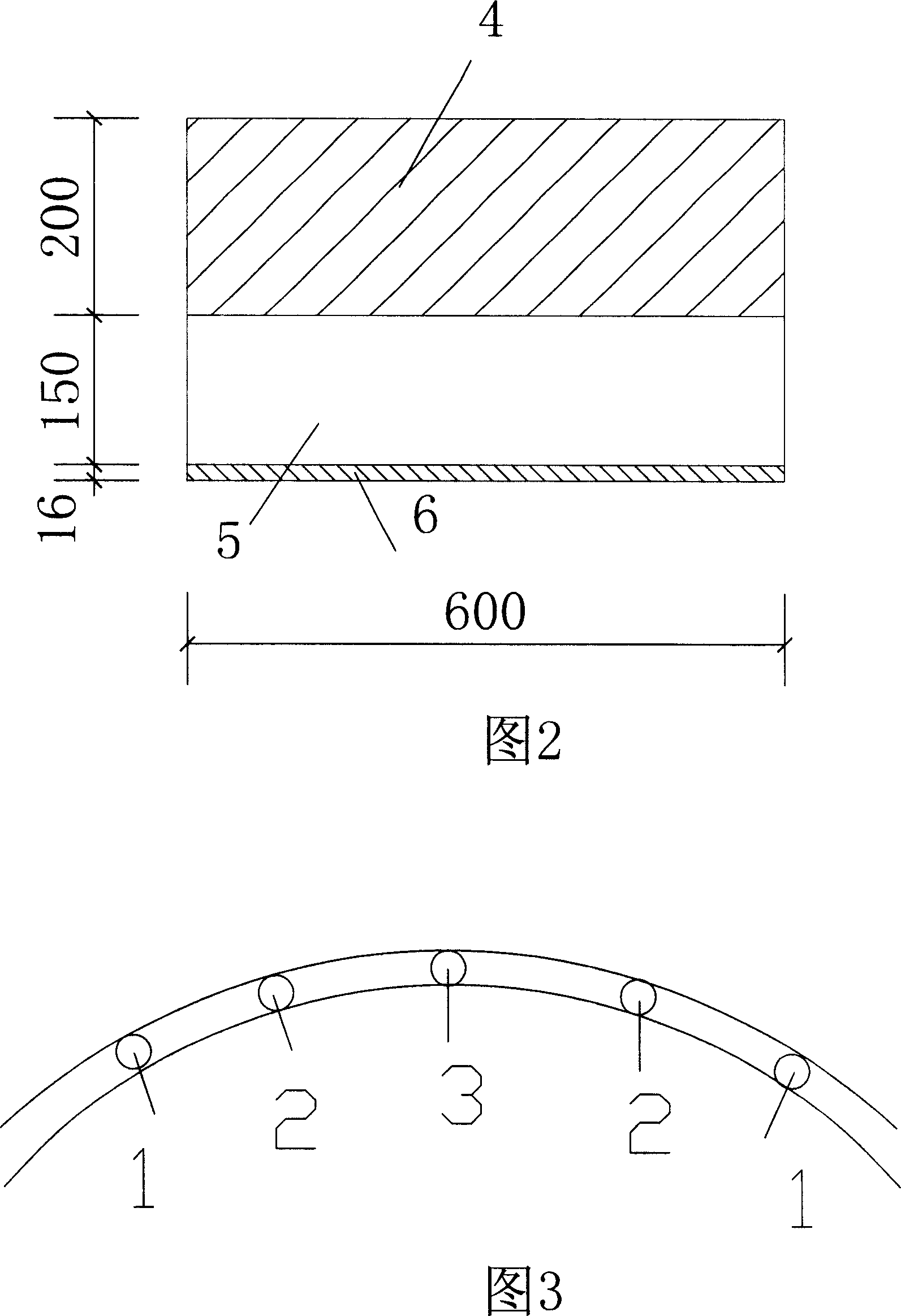
[0048] Reinforce the three-span double-curved arch bridge with equal cross-section. According to the original design data of the reinforced concrete structure, as well as the inspection and evaluation of the structure, it is decided to use steel-self-compacting concrete composite beams to strengthen the concrete arch ribs. The reinforcement design schematic diagram See Figure 2, 4 is the section of the original arch rib, 5 is the new section of the arch rib, 6 is the new steel plate, the design strength of self-compacting concrete is C35, the maximum particle size of coarse aggregate is not more than 15mm, and the slump expansion is not less than 650mm .

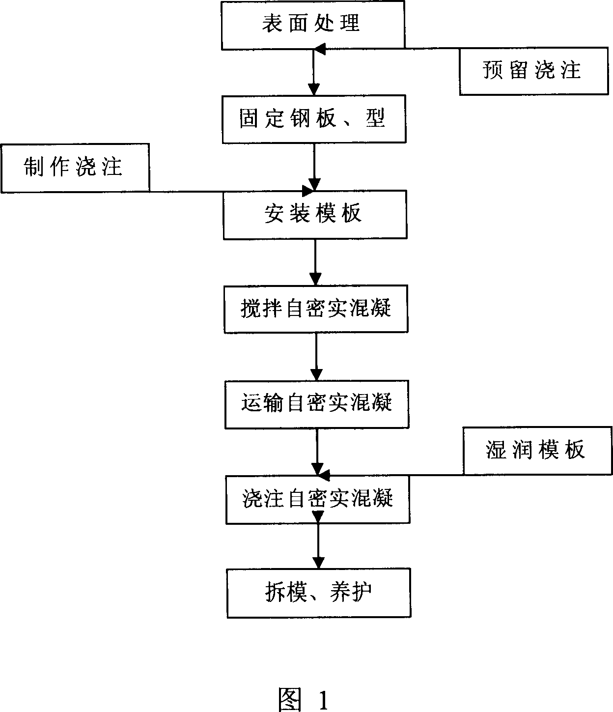
[0049] Referring to Figure 1, the technological process of steel-self-compacting concrete composite structure reinforcement technology is as follows:

[0050] 1. Treat the concrete surface of the original component with a greasy knife and a grinder, and remove the surface paint layer and decorative layer until the old concre...

Embodiment 2

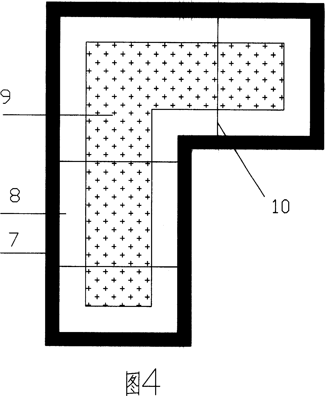
[0080] Reinforcement of a load-bearing column on the 4th floor of an 18-story residential building. Due to construction reasons, the concrete of a load-bearing column on the 4th floor of a certain 18-story residential building is loose, has no cementing ability, is of poor quality, and its strength is far lower than the design threshold. It is decided to strengthen it by steel-self-compacting concrete composite column reinforcement method. The reinforcement design is shown in Figure 4. In the figure, 7 is the newly added steel plate, 8 is the thickness of the newly added self-compacting concrete reinforced section, 9 is the original load-bearing column, and 10 is the tension steel bar. The design strength of self-compacting concrete is C50, the maximum particle size of coarse aggregate is not more than 20mm, and the slump expansion is not less than 600mm.

[0081] 1. Use the I-beam as a support to unload the four beams bearing the load of the load-bearing column, and transfer...


PUM

PropertyMeasurementUnit
Particle sizeaaaaaaaaaa
Maximum particle sizeaaaaaaaaaa
Slump spreadaaaaaaaaaa

Abstract

The invention discloses a fastening method of steel-self density concrete composite construction, which is characterized by the following: adopting steel-concrete composite structure; adopting self density concrete on concrete material; proceeding original concrete structure element surface treat; assembling steel; stirring and casting self density concrete; demoulding; curing. This invention possesses simple and stable construction, which can increase bearing capacity, stability and fatigue resistance property of the concrete structure.

Description

technical field [0001] The invention belongs to the technical field of concrete structure reinforcement engineering, and in particular relates to a steel-self-compacting concrete composite structure reinforcement construction method. technical background [0002] In my country, based on the design base period, a large number of concrete engineering structures are in the state of maintenance and reinforcement. In addition, due to the unqualified construction quality and the transformation of building functions, in recent years, concrete structure reinforcement technology has become more and more popular in China. In order to pay more attention to it, a variety of reinforcement technologies and reinforcement materials have emerged. However, with the development of large-scale and complex buildings, the reinforcement process becomes more and more complicated, and the reinforcement becomes more and more difficult. For some large buildings and some special-shaped structural compon...

Claims


Application Information

Patent Timeline
IPC IPC(8): E04G23/02
Inventor 余志武刘赞群刘运华邓德华蒋丽忠余锋彭国雄
Owner CENT SOUTH UNIV
Learn More