
Switching type voltage adjuster and slope compensation process thereof

A voltage regulator, slope compensation technology, applied in the direction of DC power input conversion to DC power output, instruments, electrical components, etc., can solve the problems of slow response speed, complicated loop compensation design, etc., to achieve a good boost effect

Inactive Publication Date: 2007-12-26
MEDIATEK INC
View PDF0 Cites 48 Cited by
  • Summary
  • Abstract
  • Description
  • Claims
  • Application Information

AI Technical Summary

Problems solved by technology

However, for transient response, since any change in the line or load must be detected by the feedback resistor divider first, and then by the error amplifier and pulse width modulation (PWM: Pulse-Width Modulation ) generator to react, so the reaction rate will be slower
Furthermore, since the output LC network will have a complex pole pair (complex-pole pair) and the loop gain will vary with the input voltage, the design of the loop compensation is even more complicated.

Method used


Image

  • Switching type voltage adjuster and slope compensation process thereof
  • Switching type voltage adjuster and slope compensation process thereof
  • Switching type voltage adjuster and slope compensation process thereof

Examples


Embodiment Construction

[0054] In order to make the above and other objects, features, and advantages of the present invention more comprehensible, a preferred embodiment is specifically cited below, together with the accompanying drawings, as follows:

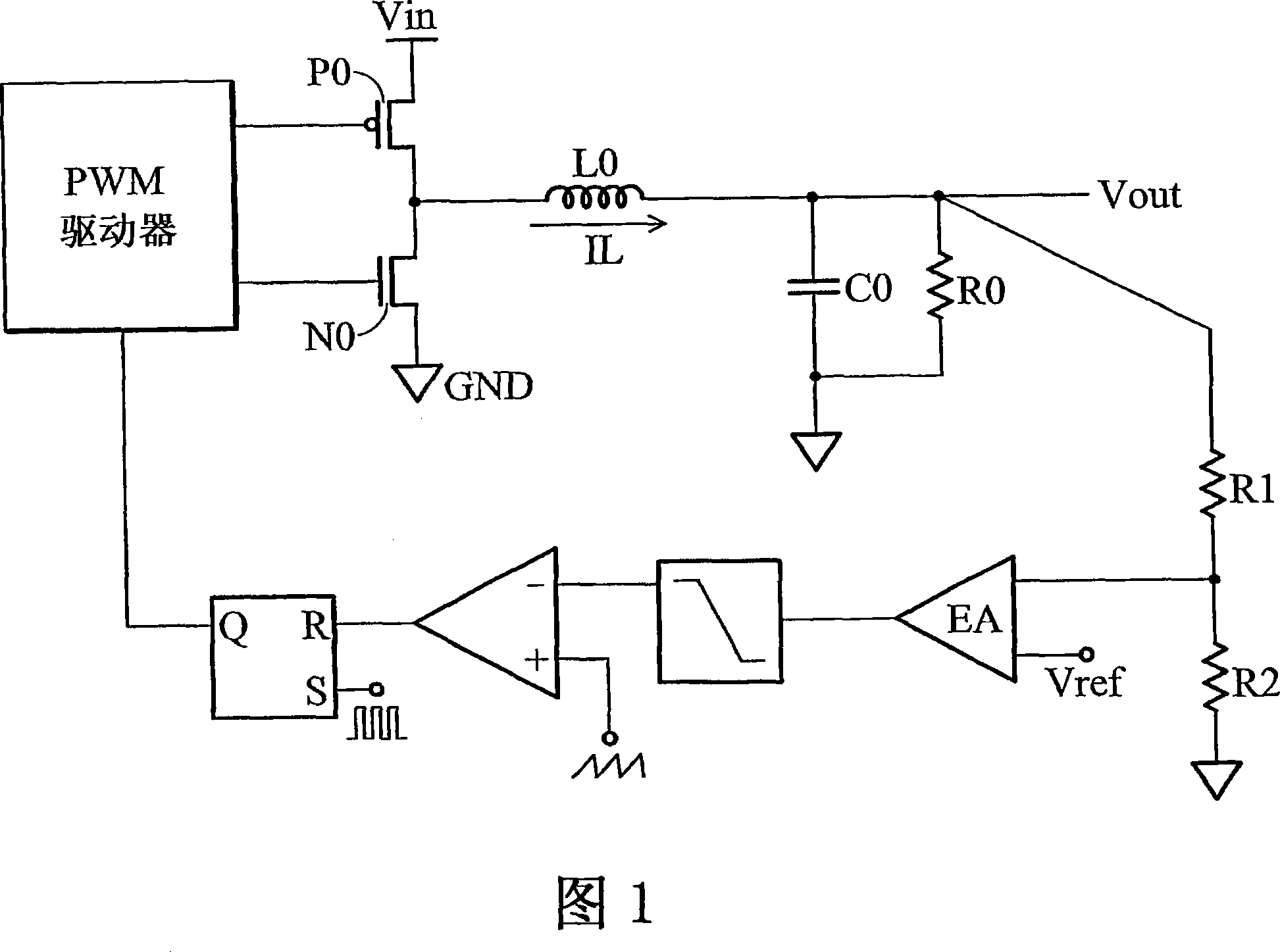
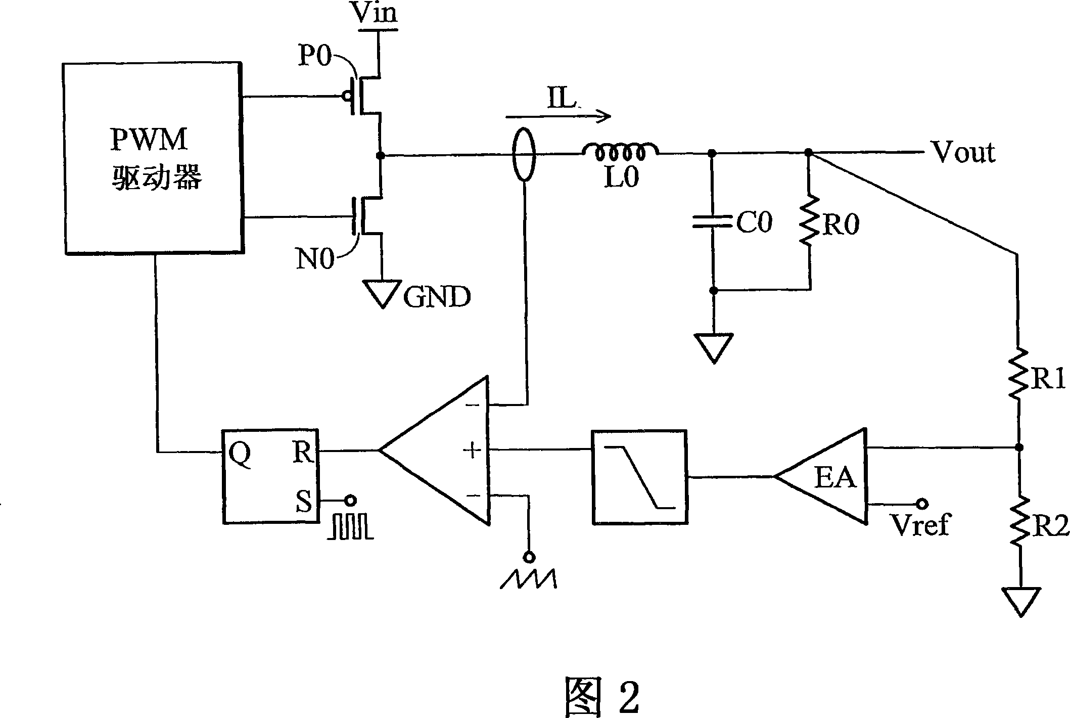
[0055] FIG. 2 shows an embodiment of a current-controlled switching voltage regulator. As shown in the figure, in addition to the feedback voltage, the continuous inductor current signal IL is also fed back to the control loop, and the inductor current signal IL is a triangular wave signal in a steady state. After comparing the inductor current signal IL with the output signal of the error amplifier (EA), a PWM driving signal is generated to control the on and off of the PWM output stage. Furthermore, in order to increase the stability, the slope compensation signal is subtracted from the inductor current signal IL, or the output signal of the error amplifier.

[0056] Because the inductor current signal related to the input and output data will be ...


PUM


Abstract

A switching voltage regulator and slope compensation method thereof are provided. The switching voltage regulator comprises an inductor coupled to a load; a pulse width modulation (PWM) unit comprising an output stage and generating a PWM driving signal to control the output stage, such that the inductor delivers an inductor current signal to the load; and a slope compensation unit outputting a slope compensation signal with a compensation slope proportional to a falling slope of the inductor current signal to the PWM unit according to the inductor current signal. The invention can perform excellent boosting, voltage reduction, and voltage transformation for the power supply.

Description

technical field [0001] The present invention relates to DC voltage conversion, in particular to a switchable voltage regulator with slope compensation and a slope compensation method thereof (Switching regulators and slope compensation method thereof). Background technique [0002] Battery life is a very important consideration in portable electronic systems, especially for consumer electronic products (such as mobile phones, digital cameras, portable computers and other handheld devices). Designers of these products must face the ever-shrinking demands of product size (and battery size) while improving battery life to match or exceed competitors' products. [0003] In order for a battery to last long, it must optimize the performance of many different electronic components, the most important of which is the voltage regulator. In portable electronic systems, voltage regulators are used to perform power processing tasks such as boosting, bucking, and transforming. [0004]...

Claims


Application Information

Patent Timeline
Patent Type & Authority Applications(China)
IPC IPC(8): H02M3/155H02M3/156
CPCH02M3/156H02M2001/0025H02M1/0025
Inventor 陈弘易刘学欣
Owner MEDIATEK INC
Learn More