
Substrate repairing device and method

A substrate and grinding belt technology, which is applied to machine tools, instruments, grinders and other directions suitable for grinding the plane of workpieces, can solve the problems of difficult grinding amount, inability to protrude 4 grinding, poor grinding of grinding substrates, etc. The effect of simplification

Inactive Publication Date: 2007-12-12
SNU PRECISION CO LTD
View PDF0 Cites 19 Cited by
  • Summary
  • Abstract
  • Description
  • Claims
  • Application Information

AI Technical Summary

Problems solved by technology

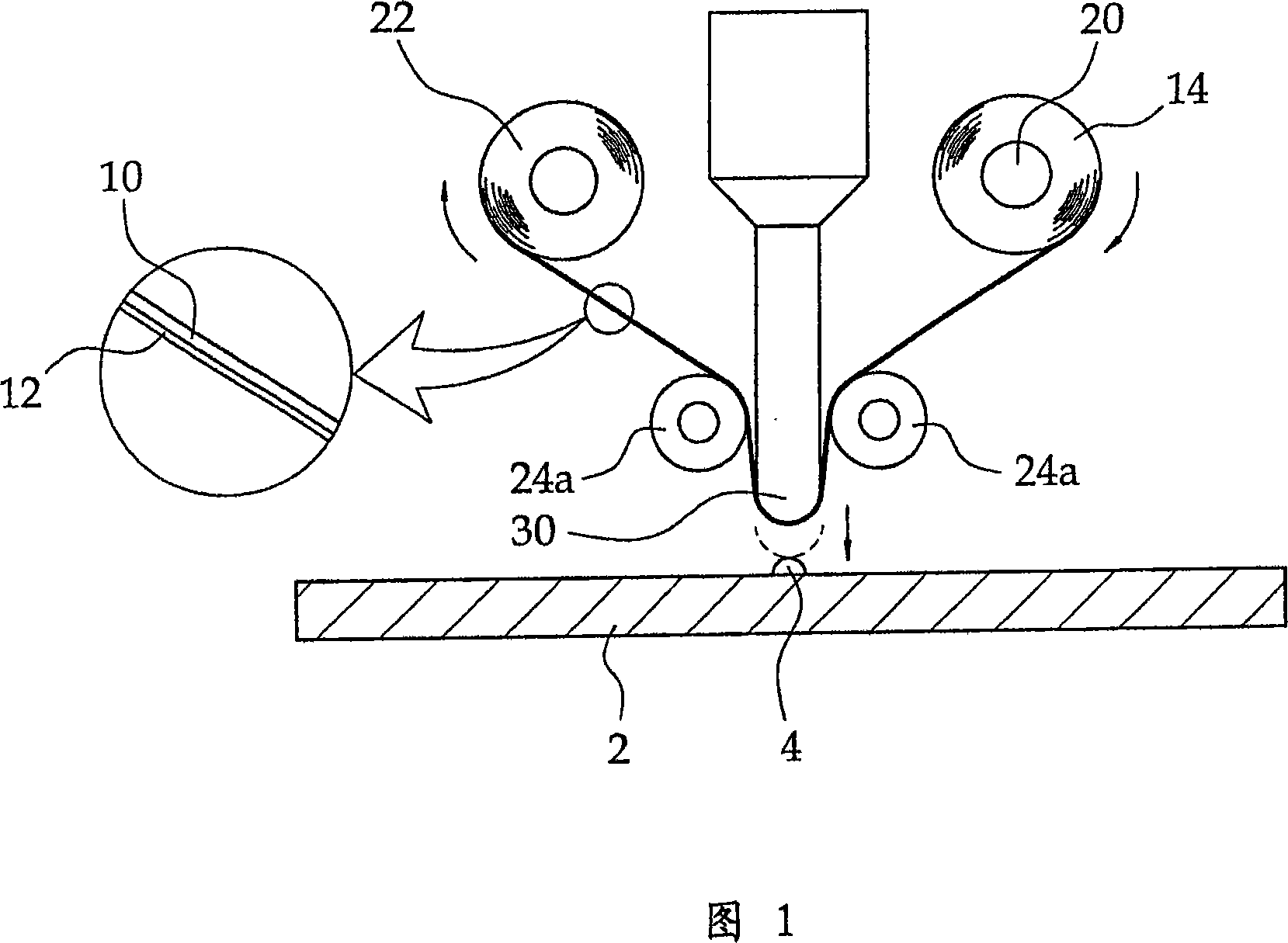
[0005] However, in the prior art substrate repairing device, it is very difficult to control the amount of grinding of the protrusion 4 determined by the lowered position of the pressing tool 30, and there is a problem that the protrusion 4 cannot be accurately ground.
In particular, when the pressing tool 30 descends in a manner consistent with the grinding amount of the protrusion 4, if the thickness of the abrasive belt 10 and the abrasive material layer 12 is not constant, the contact pressure between the protrusion 4 and the abrasive material layer 12 will fluctuations, so there is a problem that the actual grinding amount of the protrusion 4 fluctuates greatly
In addition, there is the problem that the grinding material layer 12 of the grinding belt 10 contacts the upper surface of the substrate 2 due to the excessive decline of the pressing tool 30, thereby causing poor grinding of the grinding substrate.

Method used


Image

  • Substrate repairing device and method
  • Substrate repairing device and method
  • Substrate repairing device and method

Examples


Embodiment Construction

[0024] Hereinafter, preferred embodiments of the substrate repairing apparatus and method thereof according to the present invention will be described in detail with reference to the accompanying drawings.

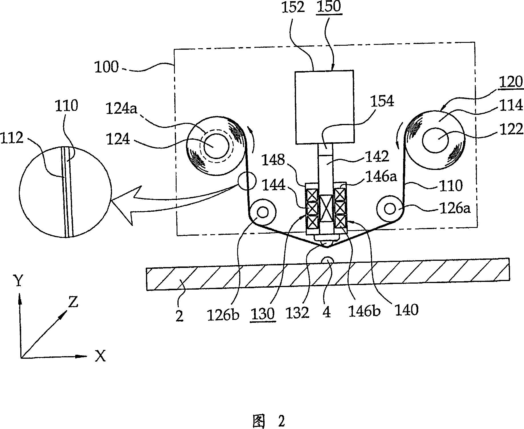
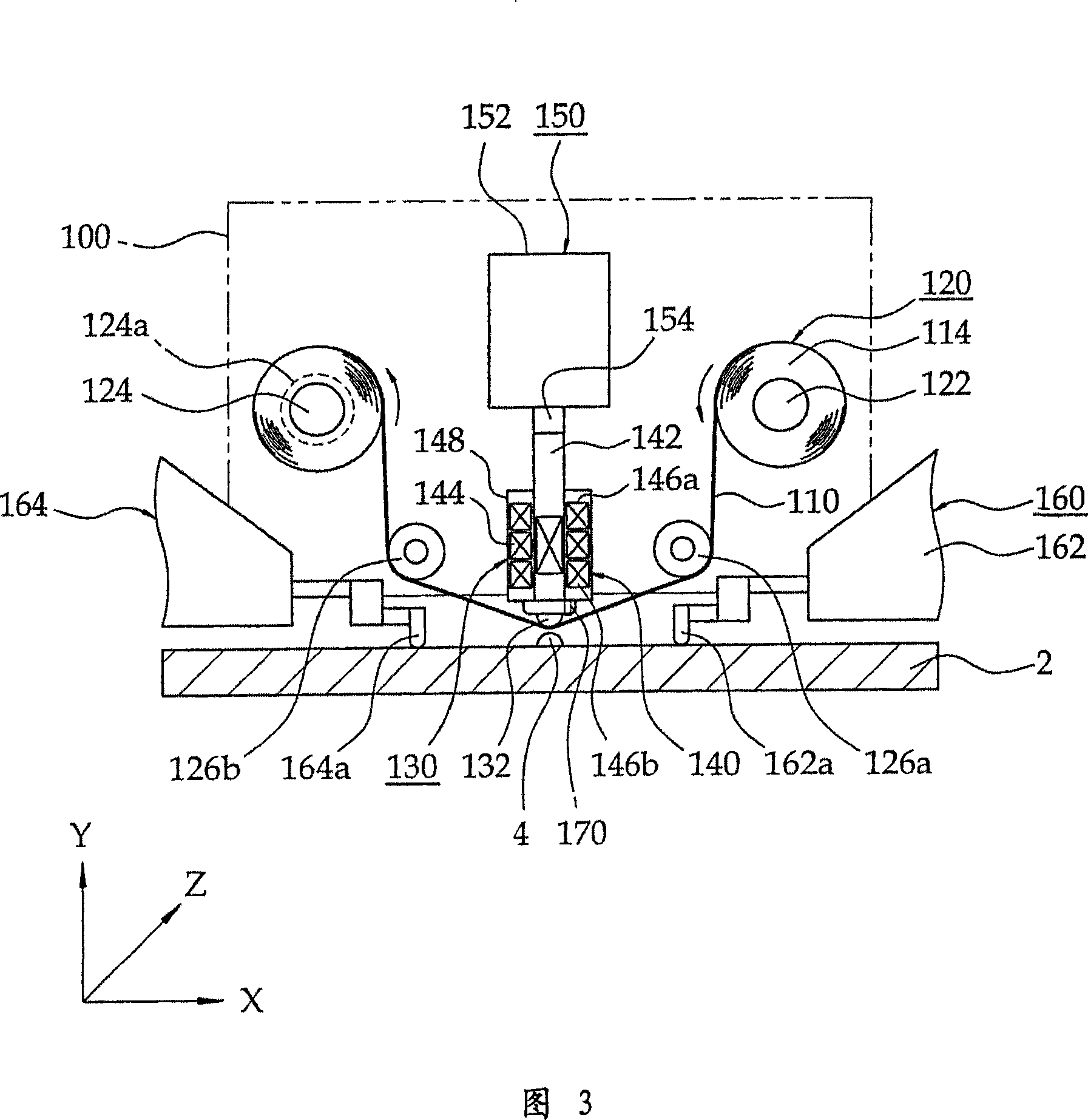
[0025] First, referring to FIG. 2 , the substrate repairing apparatus of the present invention includes a carriage (Carriage) 100 provided on the upper portion of the substrate 2 so as to move three-axis along the X-axis, Y-axis, and Z-axis directions. The three-axis motion of the carriage 100 is realized by a known automatic device having an X-axis Linear Motion Actuator, a Y-axis Linear Motion Actuator, and a Z-axis Linear Motion Actuator.

[0026] The substrate repairing apparatus according to the present invention includes a polishing tape supply device 120 for feeding the polishing tape 110 for polishing the protrusions 4 of the substrate 2 onto the protrusions 4 . The abrasive material layer 112 for actually grinding the protrusions 4 of the substrate 2 is coated on ...


PUM


Abstract

This invention relates to a repair (repair) device of a substrate, and a method for the same, which can remove in more detail the projection which exists as a defect of a substrate correctly by polish. A carriage currently installed on said substrate so that it can exercise along the X-axis, a Y-axis, and Z shaft orientations to a projection projected to a substrate. An abrasive tape feeding means which transports an abrasive tape in which said carriage is equipped and an abrasive layer is applied to the surface above said projection. A contact type displacement sensor which said carriage is equipped with so that it may be located in the upper part of said abrasive tape transported by said abrasive tape feeding means, and is provided with a presser which presses a rear face of said abrasive tape and contacts said abrasive layer to said projection, and detects said pressor displacement. A repairing device of a substrate containing a displacement control machine which controls said pressor displacement so that said pressure which it is equipped with so that it may be connected that it is pressor, and is given to said projection by said pressor press is controlled by said carriage.

Description

technical field [0001] The present invention relates to a substrate repairing device and method thereof, and more particularly to a substrate repairing device and method thereof capable of accurately removing protrusions existing as defects of the substrate by grinding. Background technique [0002] Glass Substrate is used in flat panel displays such as TFT-LCD (Thin Film Transistor-Liquid Crystal Display), PDP (Plasma Display), EL (Electroluminescence). Protrusions are formed on the surface of the glass substrate in the process of forming a color filter (ColorFilter). Protrusions generated on the surface of the glass substrate function as optical defects. Therefore, in order to improve the image quality of flat-panel displays, it is necessary to remove the protrusions of the glass substrate. [0003] Figure 1 shows a repairing device for a substrate according to the prior art. Referring to FIG. 1 , the protrusions 4 of the substrate 2 are ground by the abrasive material ...

Claims


Application Information

Patent Timeline
IPC IPC(8): B24B21/10B24B13/015B24B21/18B24B7/24
CPCB24B21/00G01N21/88G02F1/1303G02F1/1309
Inventor 李东星姜镐旻
Owner SNU PRECISION CO LTD
Learn More