
Design of three-frequency dual-circle polarization GPS microstrip patch antenna

A technology of microstrip patch antenna and dual circular polarization, which is applied to the combination of antenna units with different polarization directions, antennas, antenna supports/mounting devices, etc., and can solve the problems of hand-held vehicle troubles, high errors, and poor precision. , to achieve the effect of improving transceiver isolation, improving axial ratio performance, and compact antenna structure

Inactive Publication Date: 2007-12-05
BEIHANG UNIV
View PDF0 Cites 34 Cited by
  • Summary
  • Abstract
  • Description
  • Claims
  • Application Information

AI Technical Summary

Problems solved by technology

[0003] In common navigation applications, people hope to use an omnidirectional antenna to at least receive all visible satellite signals in the sky within five degrees above the horizon of the antenna, but the receiving range of the microstrip antenna is above the antenna, and the microstrip antenna should face the sky. This will cause trouble for handheld and car
In addition, we know that although the signal of the satellite directly above our head is better and easier to lock, the satellite directly above our head is actually the most useless. If there is no satellite with a low angle, the error will be relatively high and the accuracy will be very poor.
So based on these shortcomings, some GPS antenna users put forward restrictive requirements for low elevation gain

Method used


Image

  • Design of three-frequency dual-circle polarization GPS microstrip patch antenna
  • Design of three-frequency dual-circle polarization GPS microstrip patch antenna
  • Design of three-frequency dual-circle polarization GPS microstrip patch antenna

Examples


Embodiment Construction

[0009] Below in conjunction with accompanying drawing, describe content of the present invention in detail

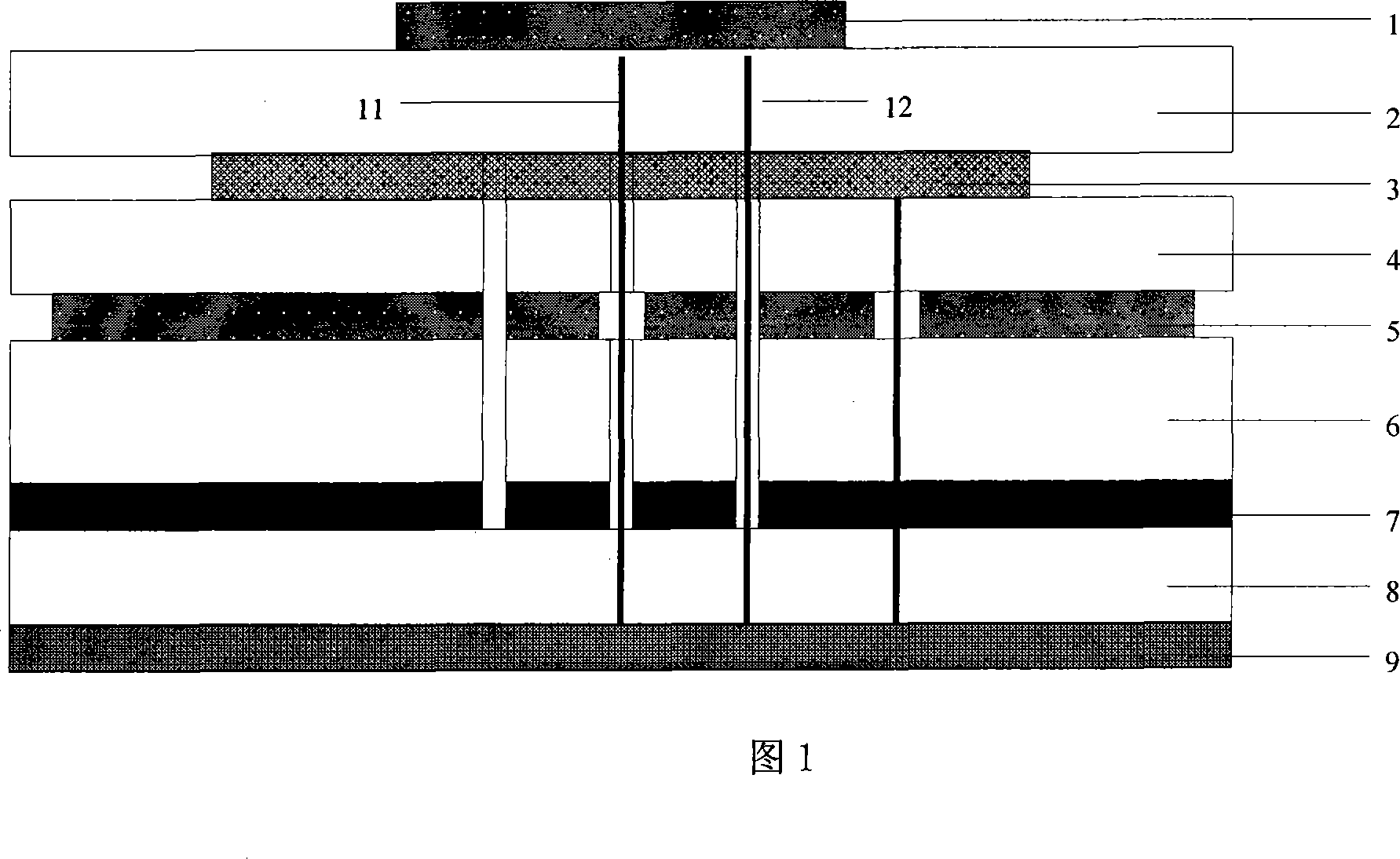
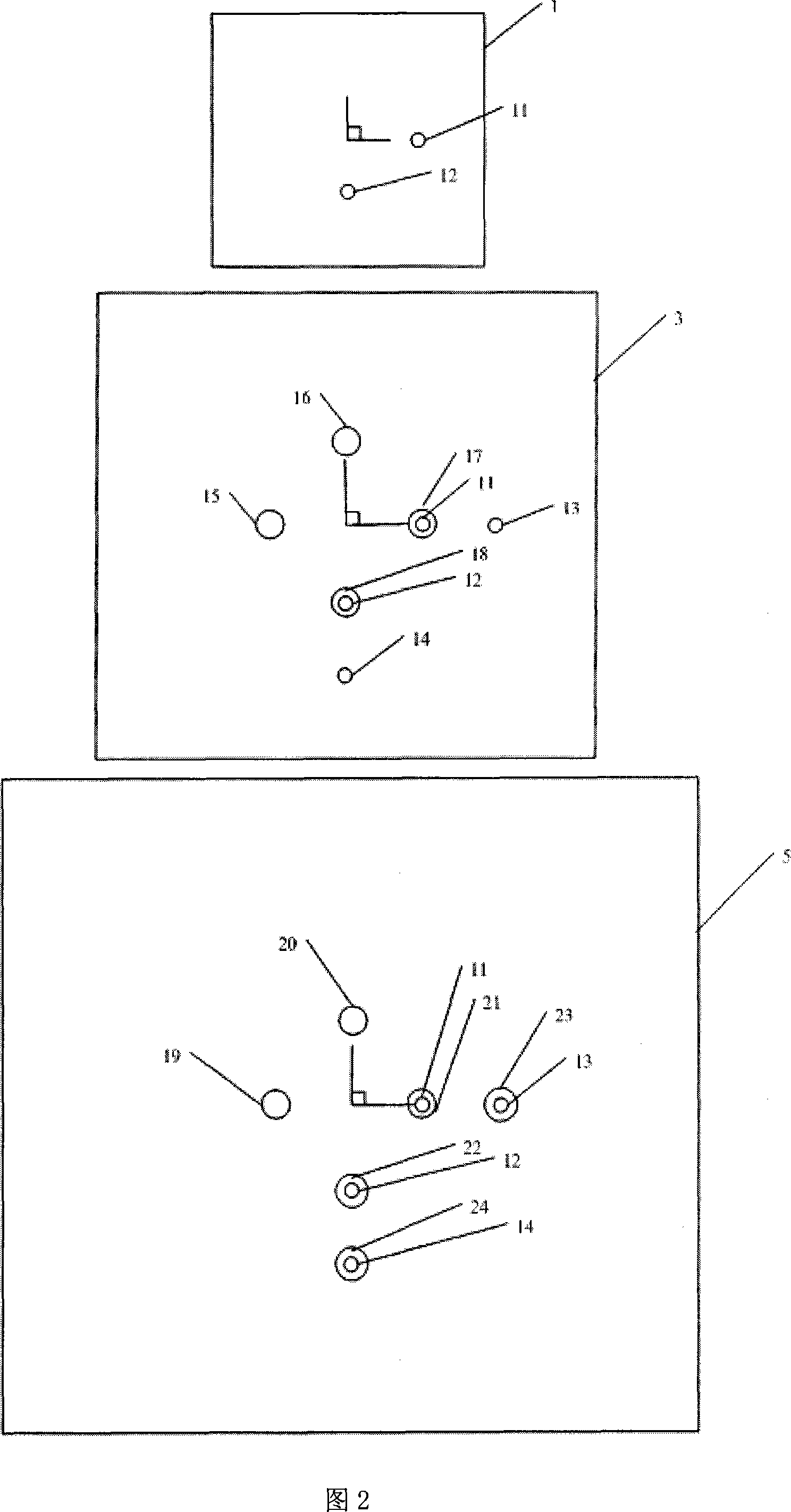
[0010] Referring to Fig. 1 and Fig. 2, the antenna consists of an upper layer patch (1), an upper layer medium (2) an intermediate layer patch (3), an intermediate layer medium (4) a lower layer patch (5), a lower layer medium (6), a floor ( 7), feed network medium (8) and feed network (9). Connect the middle layer patch (3), the middle layer medium (4), the lower layer patch (5), the lower layer medium (6), and the floor (7) with 4 symmetrical metal vias, and the probe (11) and probe The needle (12) feeds power to the upper patch through two adjacent metal vias, that is, the probe (11) and the probe (12) pass through the via hole (21) of the lower patch (5) ( 22) and the vias (17) and (18) of the interlayer patch (3). The middle layer patch (3) is directly fed by the probes (13) and probes (14), wherein the probes (13) and probes (13) pass through the holes (23) and ...


PUM


Abstract

The invention designs a three-frequency dual-circular polarization GPS microstrip patch antenna, comprising circular truncated cone metal base, feed network and stacked patch, where the stacked patch comprises lower layer, medium layer and upper layer from the bottom up, respectively resonant with three frequency ranges; the feed network comprises 3dB electric bridge and wideband power dividers, i.e. using two power dividers to implement three-frequency range three-port output, simplifying the feed network. And the highly proper circular truncated cone metal base obviously increases low elevation gain. And the invention implements simultaneous operating of three-frequency range circular polarizations, having features of wide frequency range and good low elevation gain, and suitable for vehicle-carried multi-frequency multi-port wide beam circular polarization user machine antenna.

Description

technical field [0001] The invention belongs to the technical field of antennas, and relates to a triple-frequency dual-circularly polarized GPS microstrip patch antenna, which is used for a triple-frequency vehicle-mounted antenna, such as a GPS user machine antenna in my country and a vehicle-mounted multi-frequency, multi-port, wide-beam circularly polarized user machine antenna Background technique [0002] In recent years, dual-band or multi-band working modes are usually used in some satellite systems and communication systems such as synthetic aperture radar, multi-mode mobile phones, etc., and the multi-band characteristics of microstrip antenna lines have become a research hotspot. The circularly polarized antenna can receive incoming waves of any polarization, and its radiated waves can also be received by any polarized antenna; when the circularly polarized wave is incident on a symmetrical target, the direction of rotation is reversed, so the circularly polarized ...

Claims


Application Information

Patent Timeline
IPC IPC(8): H01Q13/08H01Q1/38H01Q21/24H01Q1/12
Inventor 苗俊刚罗贤梁刘东海白冰李凤琴郝立强赵鑫
Owner BEIHANG UNIV
Learn More