Light emitting apparatus, display apparatus and method for controlling light emitting apparatus
一种发光装置、控制方法的技术,应用在非发光型显示装置,发光装置领域,能够解决不适液晶背光灯、显示装置色再现性降低、亮度和色度的变化大等问题
- Summary
- Abstract
- Description
- Claims
- Application Information
AI Technical Summary
Problems solved by technology
Method used
Image
Examples
Embodiment approach 1
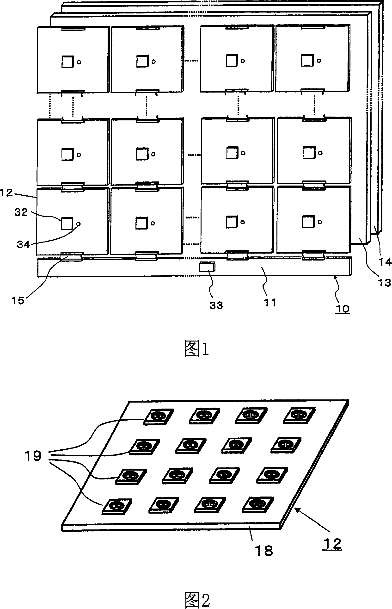
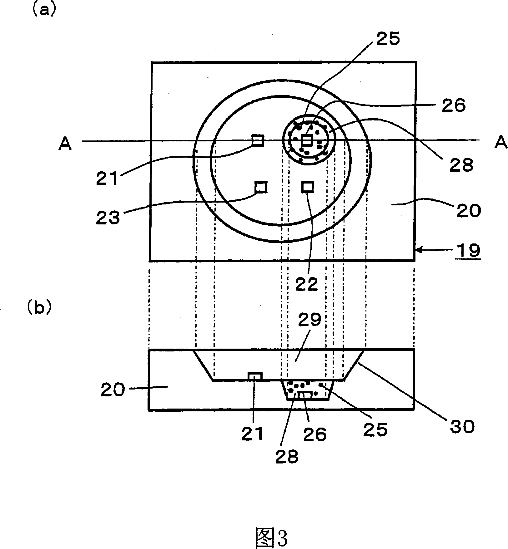
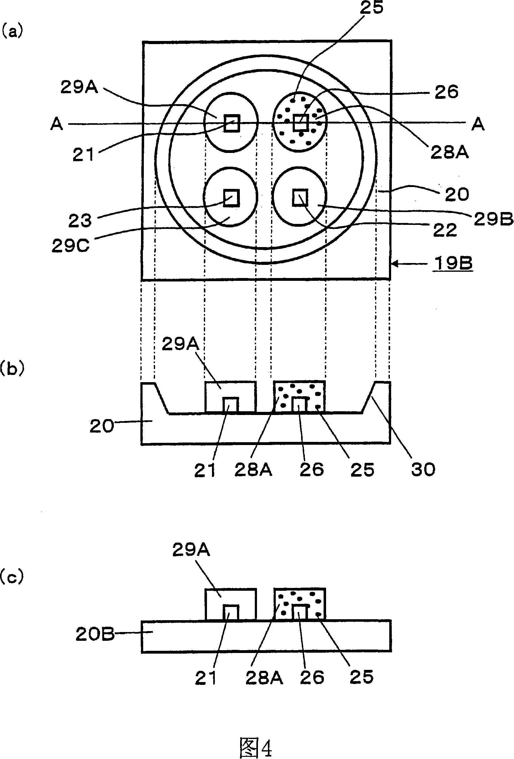
[0039] First, FIG. 1 is a configuration diagram of a liquid crystal display device 10 according to Embodiment 1. As shown in FIG. The plurality of backlight blocks 12 illuminate the liquid crystal panel 14 through the diffusion sheet 13 . A drive circuit 32 is mounted on the back surface (the surface shown in FIG. 1 ) of the backlight block 12 . A temperature sensor 34 may also be mounted. The above-mentioned temperature sensor 34 is not used when performing the first operation described below. In addition, it may be mounted on each backlight block 12 respectively, and may be mounted on one backlight block 12 or a typical backlight block 12 . The driving circuit 32 and the temperature sensor 34 are connected to the control circuit 33 through the cable 15 , and the control circuit 33 is provided on the control substrate 11 shared by all the backlight blocks 12 . In addition, even if the liquid crystal panel 14 is replaced with other non-self-luminous image display panels suc...
Embodiment approach 2
[0080] In the second embodiment, the LED group 19 in the first embodiment is replaced with the LED group 59 , and a green LED chip and a green light-emitting phosphor are also used in combination for green light emission. Color balance is achieved by using a color sensor to control the luminous ratio of LED chips and phosphors. Thus, by using a red light-emitting phosphor excellent in temperature characteristics and a green light-emitting phosphor excellent in luminous efficiency, a display device capable of obtaining high brightness even at high temperatures can be realized.
[0081] FIG. 17( a ) is a plan view of the LED group 59 , and FIG. 17( b ) is a cross-sectional view of the LED group 59 . In the package 60 , a first blue LED chip 61A, a green LED chip 62 , a second blue LED chip 61B, and a red LED chip 63 are mounted. Green light-emitting phosphors 64 are dispersed in the first resin 68A covering the first blue LED chip 61A. Red light-emitting phosphors 65 are dispe...
Embodiment approach 3
[0093] In Embodiment 3, two phosphors are excited by one blue LED chip. In this way, compared with the second embodiment described above, this embodiment can save one chip. In this embodiment, only an LED group different from Embodiment 2 and its operation will be described. In addition, the same code|symbol is attached|subjected to the same structural element.
[0094] FIG. 20( a ) is a plan view of the LED group 89 , and FIG. 20( b ) is a cross-sectional view of the LED group 89 . As shown in the figure, the structure of the LED group 89 is that two blue LED chips 91 , a green LED chip 92 and a red LED chip 93 are installed in a package 90 . Resin 98 is filled to seal the blue LED chip. The resin 98 has a two-layer structure, red light emitting phosphors 95 are dispersed in a portion close to the blue LED chip 91 , and green light emitting phosphors 94 are dispersed in a portion far from the blue LED chip 91 . This structure is advantageous in reducing the rate at which ...
PUM
| Property | Measurement | Unit |
|---|---|---|
| wavelength | aaaaa | aaaaa |
| wavelength | aaaaa | aaaaa |
| wavelength | aaaaa | aaaaa |
Abstract
Description
Claims
Application Information
 - R&D
- Intellectual Property
- Life Sciences
- Materials
- Tech Scout
- Unparalleled Data Quality
- Higher Quality Content
- 60% Fewer Hallucinations
Browse by: Latest US Patents, China's latest patents, Technical Efficacy Thesaurus, Application Domain, Technology Topic, Popular Technical Reports.
© 2025 PatSnap. All rights reserved.Legal|Privacy policy|Modern Slavery Act Transparency Statement|Sitemap|About US| Contact US: help@patsnap.com


