Switching device
A conversion device and conversion valve technology, which is applied in the direction of valve device, transportation and packaging, conveying bulk materials, etc., to achieve the effect of reducing air leakage
- Summary
- Abstract
- Description
- Claims
- Application Information
AI Technical Summary
Problems solved by technology
Method used
Image
Examples
Embodiment 1
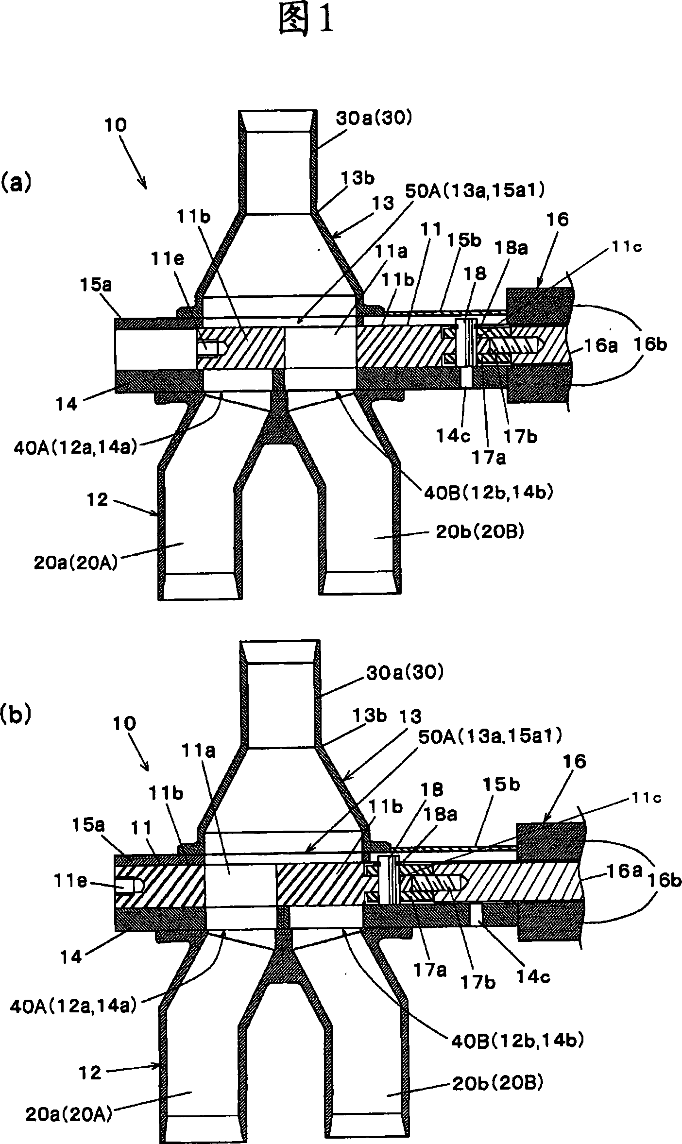
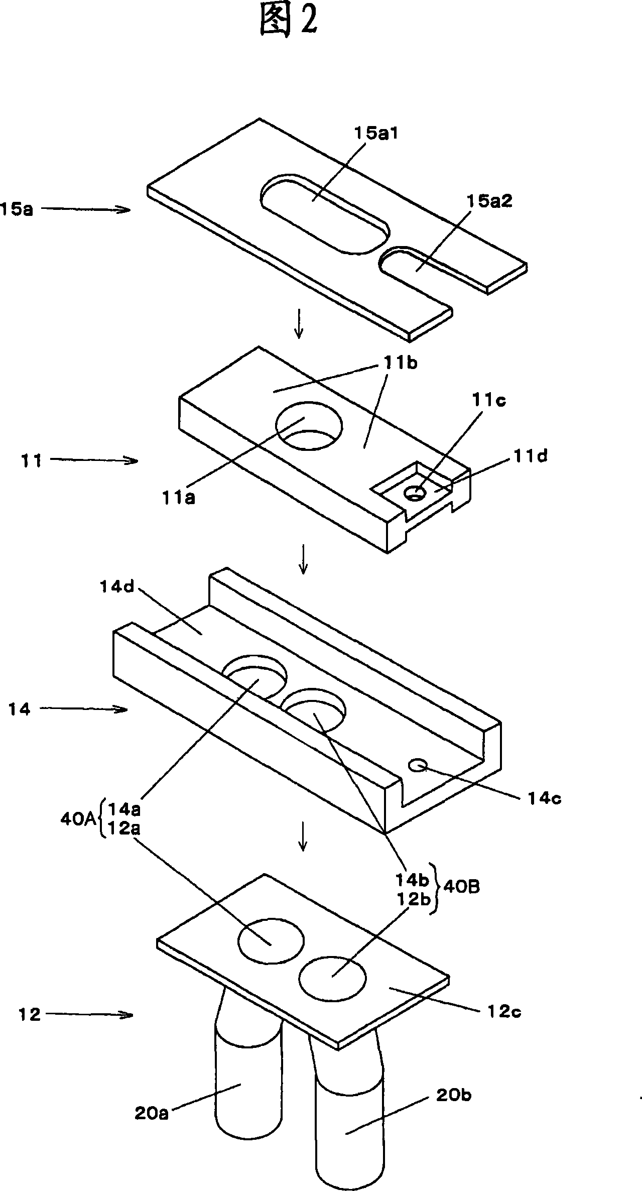
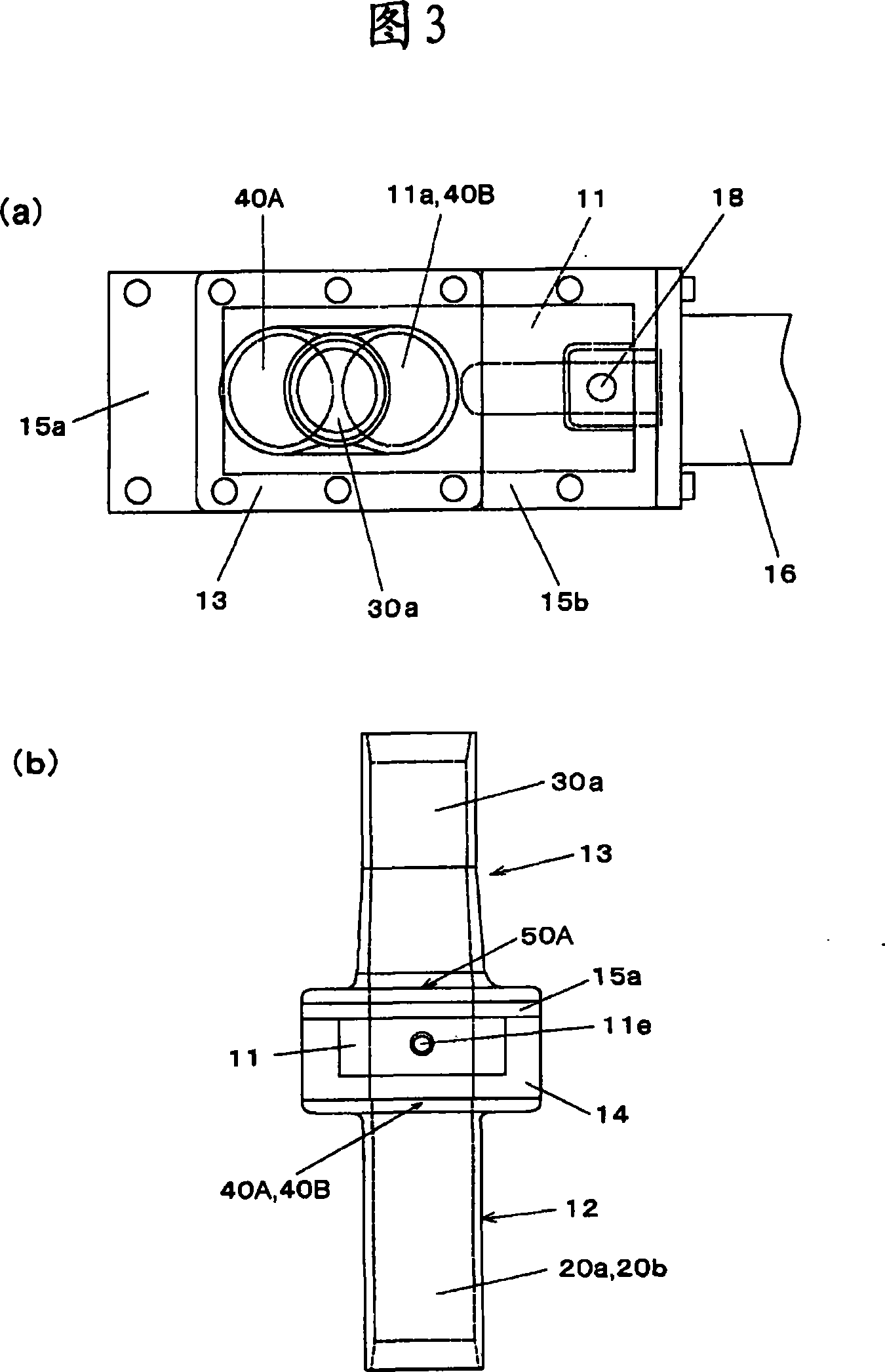
[0072] What Fig. 1 to Fig. 3 represented is an embodiment of the conversion device related to the first invention, Fig. 1 is the longitudinal sectional schematic diagram of this conversion device, (a) is the state when conveying B material, (b) is conveying A material time status. Fig. 2 is a schematic exploded perspective view of the main parts of the same device. Among Fig. 3 (a) is the plan view of same device, (b) is the left side view of same device.
[0073] The conversion device 10 shown in Fig. 1 to Fig. 3 consists of a downstream side converging pipe 13, an upper case 15a and a lower case 14 constituting the main body case, a cover 15b for maintenance, an upstream branch pipe 12, and a cylinder attached to the main body case. (Driving mechanism) 16 is constituted by the slide-type plate-shaped switching valve 11 that slides in the main body case by driving the cylinder 16 .
[0074] Here, the illustrated downstream side air conveying passage connection tube 30a cons...
Embodiment 2
[0106] What Fig. 4 to Fig. 6 showed is an embodiment of the conversion device related to the second invention, Fig. 4 is the longitudinal sectional schematic diagram of this conversion device, (a) is the state when conveying B material, (b) is conveying A material time status. Fig. 5 is a schematic exploded perspective view of the main parts of the same device. Among Fig. 6 (a) is the plan view of same device, (b) is the left side view of same device.
[0107] In addition, the difference between this embodiment and the first embodiment will be mainly described below, and the same symbols will be used for the same structures, and their descriptions will be omitted.
[0108] The conversion device 10A shown in FIGS. 4 to 6 is composed of a downstream side converging pipe 23, a lower case 24 constituting a main body case, a front cover 15c, a lower end portion of the downstream converging pipe 23 and a cover 15b, an upstream side branching pipe 22, The cylinder 16 attached to th...
PUM
 Abstract
Description
Claims
Application Information
 - R&D
- Intellectual Property
- Life Sciences
- Materials
- Tech Scout
- Unparalleled Data Quality
- Higher Quality Content
- 60% Fewer Hallucinations
Browse by: Latest US Patents, China's latest patents, Technical Efficacy Thesaurus, Application Domain, Technology Topic, Popular Technical Reports.
© 2025 PatSnap. All rights reserved.Legal|Privacy policy|Modern Slavery Act Transparency Statement|Sitemap|About US| Contact US: help@patsnap.com


