
Modular device for simulating high energy thunder amplification current

A high-energy, high-current technology, applied in the field of modular simulation of high-energy lightning and high-current devices, can solve problems such as complex operation of equipment, difficulty in success, and impossibility of application, achieving current energy and waveform compliance, simple and feasible scheme, and discharge The effect of current stabilization

Inactive Publication Date: 2010-05-19
上海万谱电器有限公司
View PDF1 Cites 0 Cited by
  • Summary
  • Abstract
  • Description
  • Claims
  • Application Information

AI Technical Summary

Problems solved by technology

Such equipment requires a large investment and complex technology, and the lightning current generated is suitable for products such as discharge gaps, but not suitable for widely used zinc oxide products. Moreover, the principle of Crowbar discharge is affected by air temperature and humidity, and there is a problem of success rate, so it is not suitable for The application of the majority of lightning protection product manufacturers and testing institutions
[0004] The existing Crowbar discharge technology mainly has the following technical deficiencies: (1) The operation of the equipment is complicated: to generate a 10 / 350us lightning current waveform, two sets of equipment must be used for joint action at the same time, and the action synchronization time is about 10us
If the operator is a little careless or the external environment changes, it will be difficult to succeed
(2) Huge investment: the investment of such a set of equipment can cost millions, and the unit price of two sets of equipment imported from China is more than four to five million.
(3) The application of the output lightning current is limited to the air gap, but it cannot be applied to the metal oxide varistors which are more widely used in the engineering field

Method used


Image

  • Modular device for simulating high energy thunder amplification current
  • Modular device for simulating high energy thunder amplification current
  • Modular device for simulating high energy thunder amplification current

Examples


Embodiment Construction

[0017] Please refer to the accompanying drawings for a further description of the present invention.

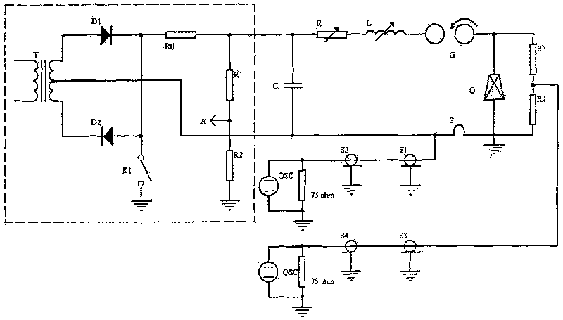
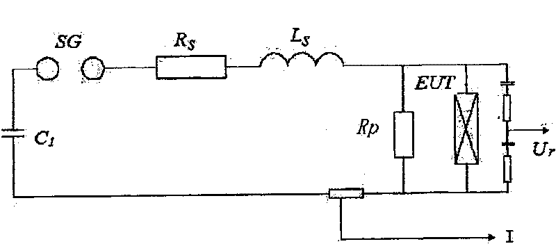
[0018] Such as figure 1 Structural schematic diagram of the present invention and figure 2 As shown in the circuit schematic diagram of the present invention, the present invention provides a modular high-energy lightning high-current device for simulating, the device includes a rectifier circuit and a charging circuit, the charging capacitor 1 in the charging circuit adopts a high-energy ratio capacitor 1, The capacitor 1 is composed of multiple parallel connections, and the structure is uniformly distributed on the circumference, that is, the barrel-shaped discharge electrode 2 is in the center of the circle, and the charging capacitor 1 is arranged radially from the center, and each capacitor 1 is discharged through the resistor 3 and the center. Electrode 2 is connected. The high-energy-ratio capacitor 1 is used as the basic unit of energy. Since the unit energy genera...


PUM


Abstract

The invention discloses a modularized analog high-power thunder big-current device, which consists of communicating circuit and charging circuit, wherein the charging capacitance in the charging circuit adopts multiple paralleling high-power specific capacitors with structure to be designed at circumferential distribution; the barrel typed discharge electrode is in the center of circle with charging capacitors irradiated distributed from center to outwards; each capacitor is connected with the central electrode through resistance which is variable; when the resistance adopts low resistance value, which produces 8-20us power pulse; when the resistance is high-resistance value, it produces 10-350us power pulse. The invention can generate thunder current at 8 / 20us and 10-350us after changingthe resistance, which shortens the changing time to less than 10min with stable discharging current.

Description

technical field [0001] The invention relates to a device for simulating lightning strikes to generate 8 / 20us, 150KA and 10 / 350us, 35KA high current / high power pulse energy, which can generate pulse waveform parameters of 8 / 20us, peak maximum power up to 150KA and pulse waveform parameters of 10 / 350us, pulse lightning with peak power up to 35KA. Background technique [0002] With the continuous deepening of people's research on the phenomenon of lightning strike, there is an urgent need for a device that can simulate the phenomenon of lightning strike. At present, the most widely used and feasible method in engineering is to charge the capacitor bank through a DC high-voltage device, and then trigger the discharge through the high-voltage electrode, control the high-voltage energy discharge parameters, and obtain the standard lightning current waveform. With the in-depth development of research fields and engineering applications, the requirements for lightning pulse devices...

Claims


Application Information

Patent Timeline
Patent Type & Authority Patents(China)
IPC IPC(8): H02M9/04
Inventor 金志华韩忠明
Owner 上海万谱电器有限公司
Learn More