
Method for time synchronization in distributed control system

一种分布式控制、时间同步的技术,应用在时分多路复用系统、传输系统、同步装置等方向,能够解决同步误差增加、同步误差积累等问题

Inactive Publication Date: 2007-11-07
SAMSUNG ELECTRONICS CO LTD
View PDF0 Cites 11 Cited by
  • Summary
  • Abstract
  • Description
  • Claims
  • Application Information

AI Technical Summary

Problems solved by technology

Therefore, the synchronization error is accumulated when passing the bridge, and the synchronization error will increase exponentially

Method used


Image

  • Method for time synchronization in distributed control system
  • Method for time synchronization in distributed control system
  • Method for time synchronization in distributed control system

Examples


Embodiment Construction

[0034] Hereinafter, exemplary embodiments of the present invention will be described in detail with reference to the accompanying drawings. In the following description, many specific items such as detailed parts are shown, but these items are only used to help a comprehensive understanding of the present invention, those skilled in the art should understand that: without departing from the scope and spirit of the present invention, various The specific items to be modified.

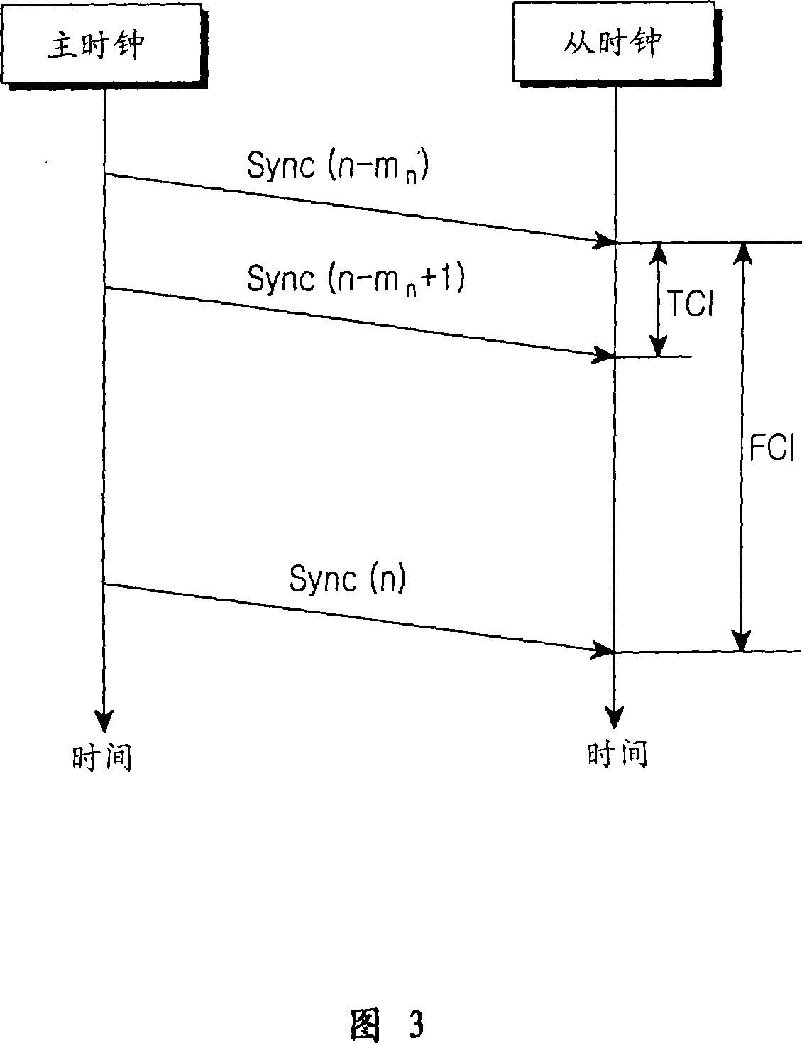
[0035]FIG. 3 is a flow chart illustrating basic operations of a Time Offset Compensation Interval (TCI) and a Frequency Compensation Interval (FCI) for display time synchronization in a distributed control system according to an embodiment of the present invention. Referring to FIG. 3 , in a time synchronization scheme according to an embodiment of the present invention, a master clock periodically transmits sync including its own startup time to a slave clock, thereby performing operations for time sync...


PUM


Abstract

A method for time synchronization in a distributed control system includes the steps of: when a sync is received from a master-side, confirming both a reception time point of the corresponding sync and a compensation time point of a previous frequency, and determining if a result obtained by confirming the two time points corresponds to a preset Frequency Compensation Interval (FCI); performing only a time offset compensation operation when the result obtained by confirming the two time points does not correspond to the preset FCI; and performing both time offset and frequency compensation operations when the result obtained by confirming the two time points corresponds to the preset FCI.

Description

technical field [0001] The present invention relates to a method of providing time synchronization in a distributed control system. Background technique [0002] Typically, a distributed control system includes a set of nodes interconnected by one or more network communication links. The network communication links may include packet links such as Ethernet or one or more of various packet links that may be employed in distributed control system applications. In distributed control systems, there has recently been a growing awareness of the need to support time-sensitive traffic. Therefore, it is necessary to synchronize the clocks among the nodes of the distributed control system. [0003] In a distributed control system involving multiple clocks, time synchronization must be employed in order to reduce the inherent instability in the source oscillator and to reduce the effects of time drift in the operating environment conditions (see Reference 1 b...

Claims


Application Information

Patent Timeline
Patent Type & Authority Applications(China)
IPC IPC(8): H04B7/26H04J3/06H04L12/56H04L29/06
CPCH04J3/0664H04L7/02
Inventor 王四海赵宰宪黄星泽金薰
Owner SAMSUNG ELECTRONICS CO LTD
Learn More