Sheet material cutting method

A cutting method and cutting direction technology, applied in electrical components, metal processing, circuits, etc., can solve the problems of easy breakage at the end of the blade, wrinkling of the sheet S, breakage of the wafer W, etc.

Active Publication Date: 2010-09-01
LINTEC CORP
View PDF8 Cites 0 Cited by
  • Summary
  • Abstract
  • Description
  • Claims
  • Application Information

AI Technical Summary

Problems solved by technology

However, in this method, as shown in FIG. 8(B), there arises such a disadvantage that when the blade 50A is inserted, the blade end is easily broken due to the thickness and / or hardness of the sheet S.
[0008] like Figure 9 As shown, in the case where the blade 50 is inclined after the blade 50A is inserted into the sheet S in a vertical posture, there is a disadvantage that the sheet S on the wafer W is wrinkled according to the amount of deviation of the blade 50A, or in some The disadvantage that the wafer W may break in case

Method used


Image

  • Sheet material cutting method
  • Sheet material cutting method
  • Sheet material cutting method

Examples


Embodiment Construction

[0046] Now, embodiments of the present invention will be described with reference to the drawings.

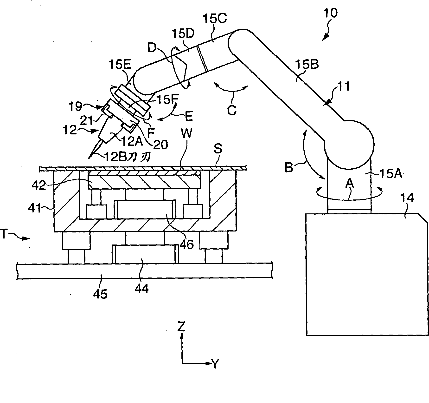
[0047] figure 1 is a schematic front view of a sheet cutting apparatus 10 and a table T provided together with the sheet cutting apparatus 10 according to an embodiment of the present invention. The table T supports the wafer W as a plate-like object in a substantially horizontal posture, so that the adhesive protective sheet S is stuck to the upper surface (circuit surface) of the wafer W, wherein the wafer W has a substantially circular shape in plan view. shaped shape. refer to figure 1 , the sheet cutting apparatus 10 includes a multi-joint manipulator 11 and a blade 12 held by the manipulator 11 .

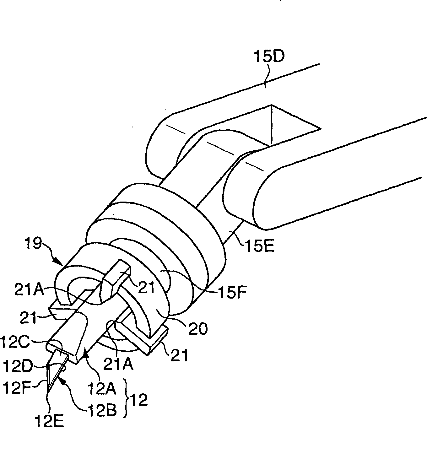
[0048] The manipulator 11 includes a base portion 14, first to sixth arms 15A-15F mounted to the upper surface side of the base portion 14 to rotate in directions indicated by arrows A-F, respectively, and a front end connected to the sixth arm 15F (that is, the manipulato...


PUM


Abstract

A sheet material cutting method, thereinto, after the said sheet material(S) is adhered on the semiconductor wafer(W), according to the shape of the semiconductor wafer(W), the part of the sheet material(S) projecting from the semiconductor wafer(W)'s periphery is cut by the blade(12). In this cutting method, the trajectory of blade(12B) is preset as canonical path in order to make blade(S) not project out of the semiconductor wafer(W). When performing the cutting operation, at the starting point(P) far from the canonical path, the edge(12B) of the blade(12) is inserted into the sheet material(S). During the process of moving near the points of the canonical path, the posture of blade(12) is adjusted according to the preconcerted toe-in angle(alpha 1), camber angle(alpha 2), back rake(alpha 3).

Description

technical field [0001] The present invention relates to a sheet cutting method, in particular to a sheet cutting method in which a sheet having a size protruding from the periphery of a plate-shaped object is pasted on the plate-shaped object, and then the sheet is cut according to the shape of the plate-shaped object . Background technique [0002] Generally, a semiconductor wafer (hereinafter simply referred to as a "wafer") is pasted with a protective sheet to protect the circuit surface located on the front side. [0003] Apply and cut this protective sheet in the following manner. That is, a protective sheet having a size protruding from the periphery of the wafer is first pasted on the wafer, and then a blade is moved along the periphery of the wafer to cut the protective sheet according to the shape of the wafer (for example, refer to Patent Document 1). [0004] [Patent Document 1] Japanese Patent No. 2919938 [0005] However, in the sheet cutting method disclosed...

Claims


Application Information

Patent Timeline
Patent Type & Authority Patents(China)
IPC IPC(8): H01L21/00H01L21/304H01L21/301H01L21/78B26D1/00B26D5/00B26D3/10
CPCH01L21/02H01L21/67132
Inventor 栗田刚
Owner LINTEC CORP
Why Eureka
Try Eureka