Fuel cell stack

一种燃料电池组、单体电池的技术,应用在燃料电池分组、燃料电池、燃料电池的零部件等方向,能够解决难单体电池移动等问题

Inactive Publication Date: 2014-04-16
HONDA MOTOR CO LTD
View PDF5 Cites 6 Cited by
  • Summary
  • Abstract
  • Description
  • Claims
  • Application Information

AI Technical Summary

Problems solved by technology

As described above, since the fastening load is applied in the stacking direction of the single cells by the fastening member, the movement of the single cells in the stacking direction is difficult to occur.

Method used


Image

  • Fuel cell stack
  • Fuel cell stack
  • Fuel cell stack

Examples


Embodiment Construction

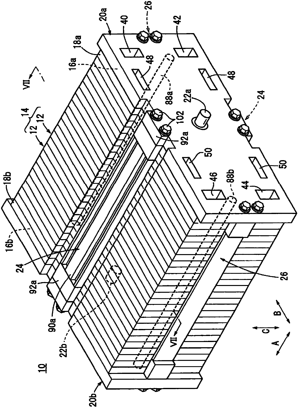
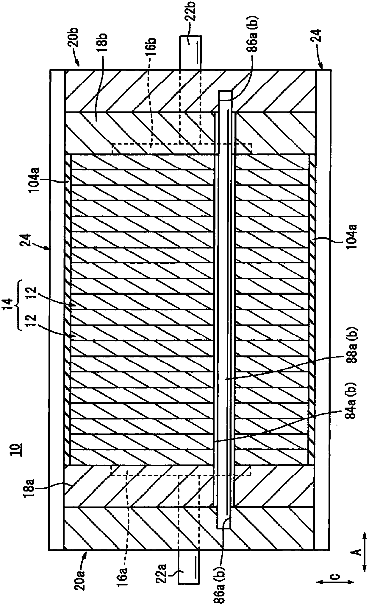
[0034] figure 1 is a schematic overall perspective view of the fuel cell stack 10 according to the present embodiment, figure 2 is its partial cross-sectional side view. The fuel cell stack 10 is mounted on a vehicle body (not shown) and used as a driving source for travel. It should be noted that the direction of the arrow A is consistent with the width direction of the vehicle body, and the direction of the arrow B is consistent with the driving direction. In addition, the arrow C direction indicates a vertical direction.

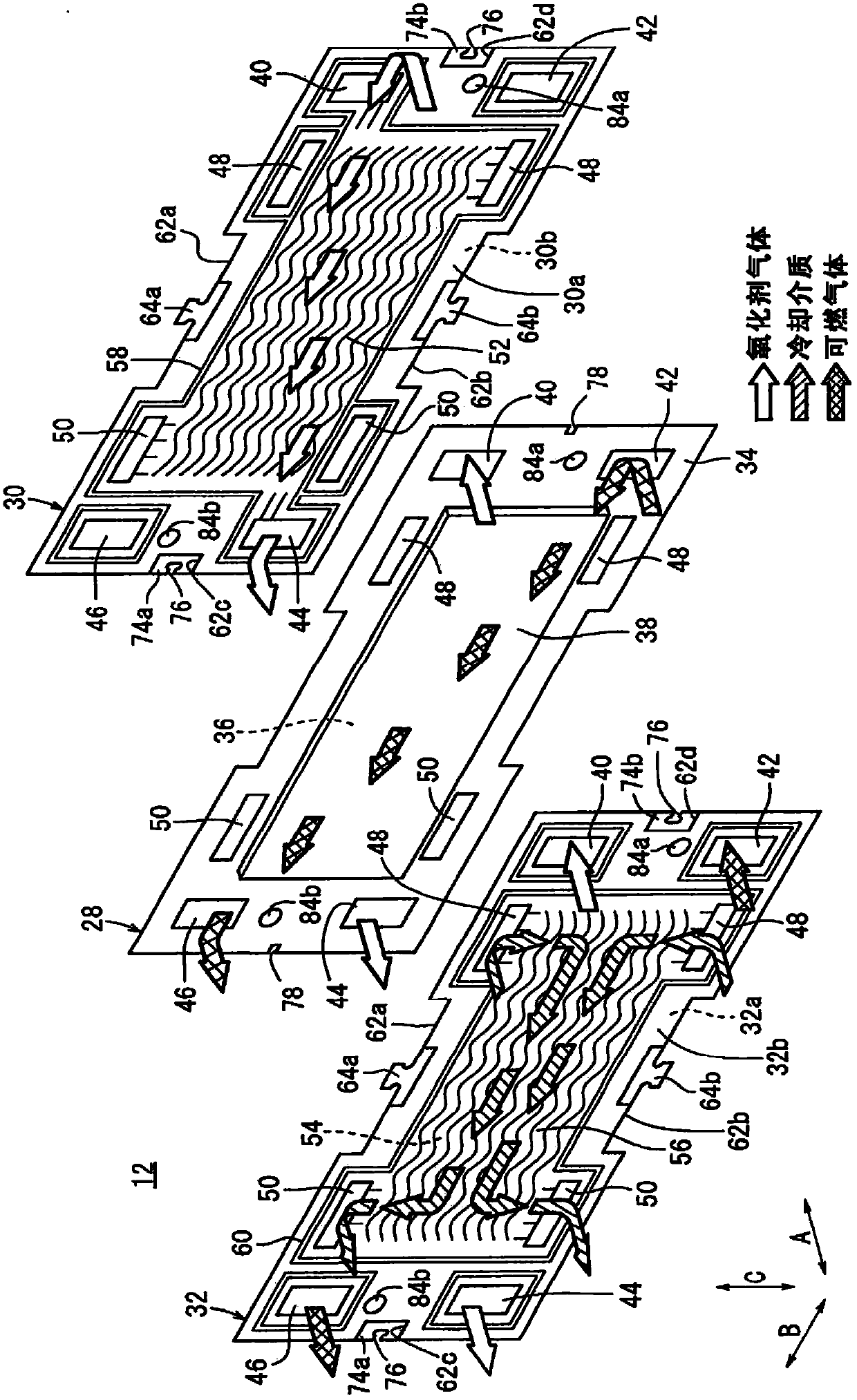
[0035] Depend on figure 1 and figure 2 It is known that the fuel cell stack 10 includes a stacked body 14 formed by stacking a plurality of unit cells 12 along the arrow A direction. Further, at one end of the stacked body 14 in the stacking direction, the first terminal plate 16a, the first insulating plate 18a, and the first end plate 20a are arranged in this order from the inner side to the outer side. Similarly, at the other end in the laminat...


PUM


Abstract

A unit cell (12) of a fuel cell stack (10) includes separators (30,32). Load receivers (64a,64b) provided in the separators (30,32) include projections (68), for example. The proximal ends of the projections (68) are depressed to form inner curves (70a,70b). In the structure, sufficient flexibility of the projection (68) is achieved. That is, when a force in a direction perpendicular to a stacking direction of fuel cell stack (10) is applied to the projection, the projection (68) is deformed in the direction perpendicular to the stacking direction.

Description

technical field [0001] The present invention relates to a fuel cell stack constituted by stacking a plurality of single cells. Background technique [0002] A fuel cell has a unit cell in which an electrolyte membrane-electrode structure is interposed between a set of separators by an anode electrode and a cathode electrode sandwiching an electrolyte (for example, a solid polymer electrolyte membrane, an oxide ion conductor). Usually, a fuel cell stack is formed by stacking a plurality of these unit cells. Generally, a fuel cell stack is provided with a fastening member that applies a fastening load from a unit cell at one end to a unit cell at the other end to prevent the unit cells from falling off. [0003] Shock loads are sometimes applied to such fuel cell stacks from the outside. As described above, since the fastening load is applied in the stacking direction of the single cells by the fastening member, movement of the single cells in the stacking direction is diffi...

Claims


Application Information

Patent Timeline
Patent Type & Authority Applications(China)
IPC IPC(8): H01M8/24
CPCH01M8/2465Y02E60/50H01M8/241H01M8/248H01M8/0206H01M8/0221H01M8/0223H01M8/0247H01M2008/1095H01M8/2483
Inventor 山野尚纪杉浦诚治和知大介
Owner HONDA MOTOR CO LTD
Why Eureka
Try Eureka