
Protection film separation head unit and equipment with same

A technology of protective film and head unit, applied in the direction of polarizing elements, layered products, chemical instruments and methods, etc., can solve the problems of increased time, inability to perform protective film separation steps smoothly, and prolonging the overall bonding time

Inactive Publication Date: 2007-10-31
SFA ENG CORP
View PDF0 Cites 1 Cited by
  • Summary
  • Abstract
  • Description
  • Claims
  • Application Information

AI Technical Summary

Problems solved by technology

Therefore, various process defects may occur, for example, the protective film separation step cannot be performed smoothly
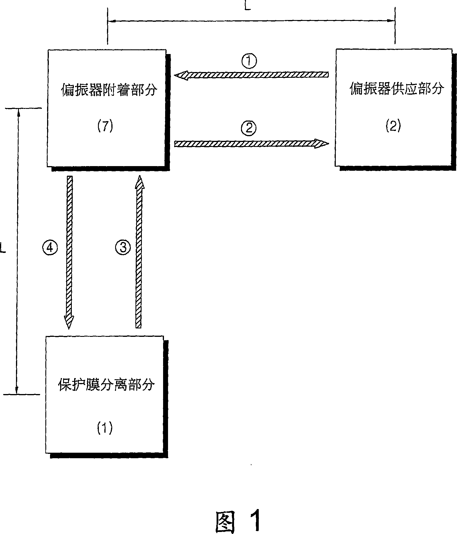
[0019] Also, due to the extensive time required for conventional protective film separation steps, bonding time is often extended
That is, although other steps such as attaching a polarizer can be quickly performed, the overall bonding time is prolonged and productivity is reduced due to the increased time for performing the protective film separation step

Method used


Image

  • Protection film separation head unit and equipment with same
  • Protection film separation head unit and equipment with same
  • Protection film separation head unit and equipment with same

Examples


Embodiment Construction

[0045] In order to gain a full understanding of the invention, its advantages and objects achieved by its embodiments, refer to the accompanying drawings, which illustrate preferred embodiments of the invention. Hereinafter, the present invention will be described in detail by explaining preferred embodiments of the invention with reference to the accompanying drawings. The same reference numerals in the figures denote the same elements.

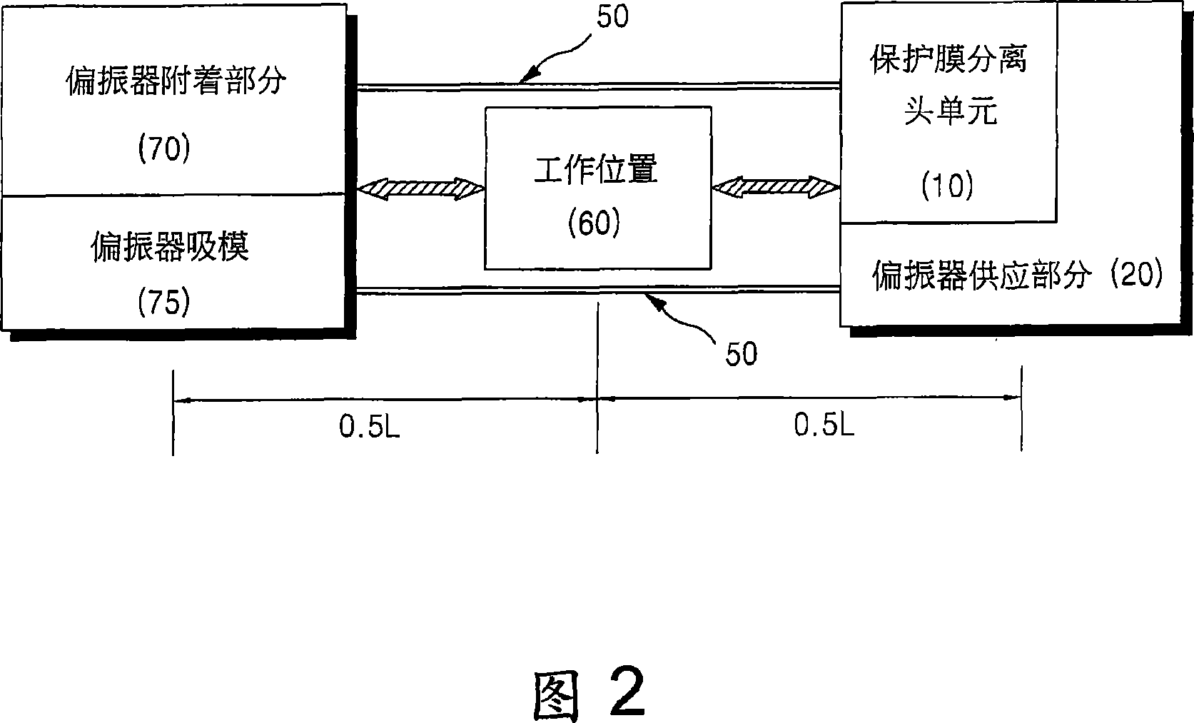
[0046] FIG. 2 illustrates the configuration of a polarizer attaching device according to an embodiment of the present invention. FIG. 3 is a partially enlarged perspective view of the polarizer attaching device of FIG. 2 .

[0047] Referring to FIGS. 2 and 3, the polarizer attaching device according to the present embodiment includes: a polarizer attaching part 70 to which a movable polarizer suction mode 75 is coupled; and a polarizer supply part 20, a protective film The separation head unit 10 is integrally coupled to the polarizer supp...


PUM


Abstract

The invention provides a polarimeter attaching device, comprising: polarimeter supporting part for supporting the polarimeter whose attached the protective film on at least one surface to the predetermined work position for separating protective film; protective film separating head unit which couples to one side of the polarimeter supporting unit and is able to move together with the polarimeter supporting unit to the work position and separate the protective film and polarimeter. The protective film separating unit comprises: unit main body; supporting roller coupling to the unit main body and supporting adhesive band; collecting roller supporting and collecting the exhausted adhesive band in the position separated from the supporting roller; and contacting roller forming adhesive band in the terminal port of the unit main body and moving from the supporting roller to the collecting roller and allowing the adhesive band contacting protective film. When the adhesive band is fixed on unit main body coupling the supporting roller, collecting roller and contacting roller, the protective film separating head unit may detachably couple to the predetermined head unit supporting portion.

Description

technical field [0001] The present invention relates to a protective film attaching unit and an apparatus having the protective film attaching unit for attaching a polarizer to a liquid crystal display (LCD) panel, and more particularly, to a unit structure that can be simplified, A protective film attaching unit with reduced footprint and shortened bonding time and an apparatus for attaching a polarizer to an LCD panel having the protective film attaching unit. Background technique [0002] Polarizers are attached to both sides of the LCD panel, and selectively transmit only light vibrating violently in a specific direction among light transmitted through the panel. Polarizers are produced at the manufacturing plant by attaching protective films to both sides of the polarizer. Therefore, at the LCD panel assembly factory, before attaching the polarizer to the LCD panel, the protective film of the polarizer is removed manually or using an adhesive tape by a worker. However...

Claims


Application Information

Patent Timeline
IPC IPC(8): G02B5/30B32B38/10G02F1/1333G02F1/1335
CPCB65B69/0025G02F1/1303G02F1/133528
Inventor 咸珉洙金东昱李龙柱尹武烈
Owner SFA ENG CORP
Learn More