Suspended carriage for wind energy facility, rotary connecting device for wind egergy facility, wind egergy facility, driving method for wind egergy facility
A technology of rotating connectors and pods, which is applied to wind turbines, wind power generators, and wind turbines in the same direction as the wind. It can solve the problems of wind energy facilities, such as shutdown economy, loss, and large size, and achieve low cost and easy monitoring. Effect
- Summary
- Abstract
- Description
- Claims
- Application Information
AI Technical Summary
Problems solved by technology
Method used
Image
Examples
Embodiment Construction
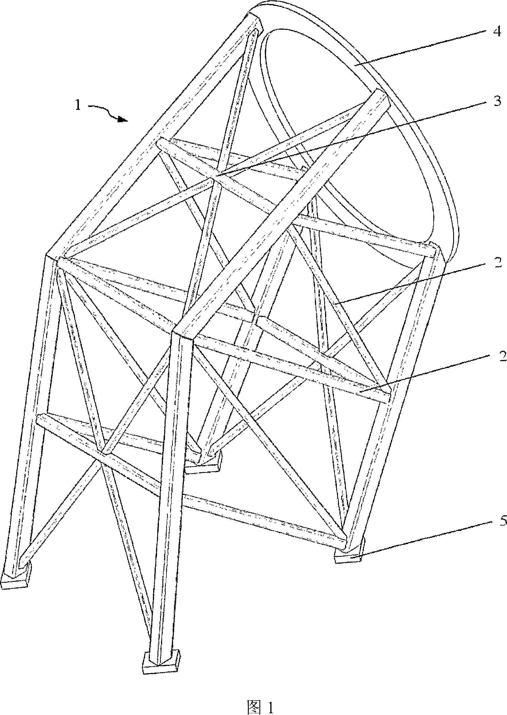
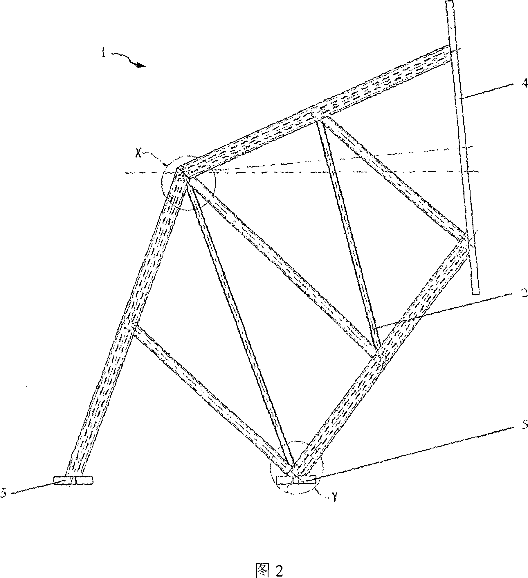
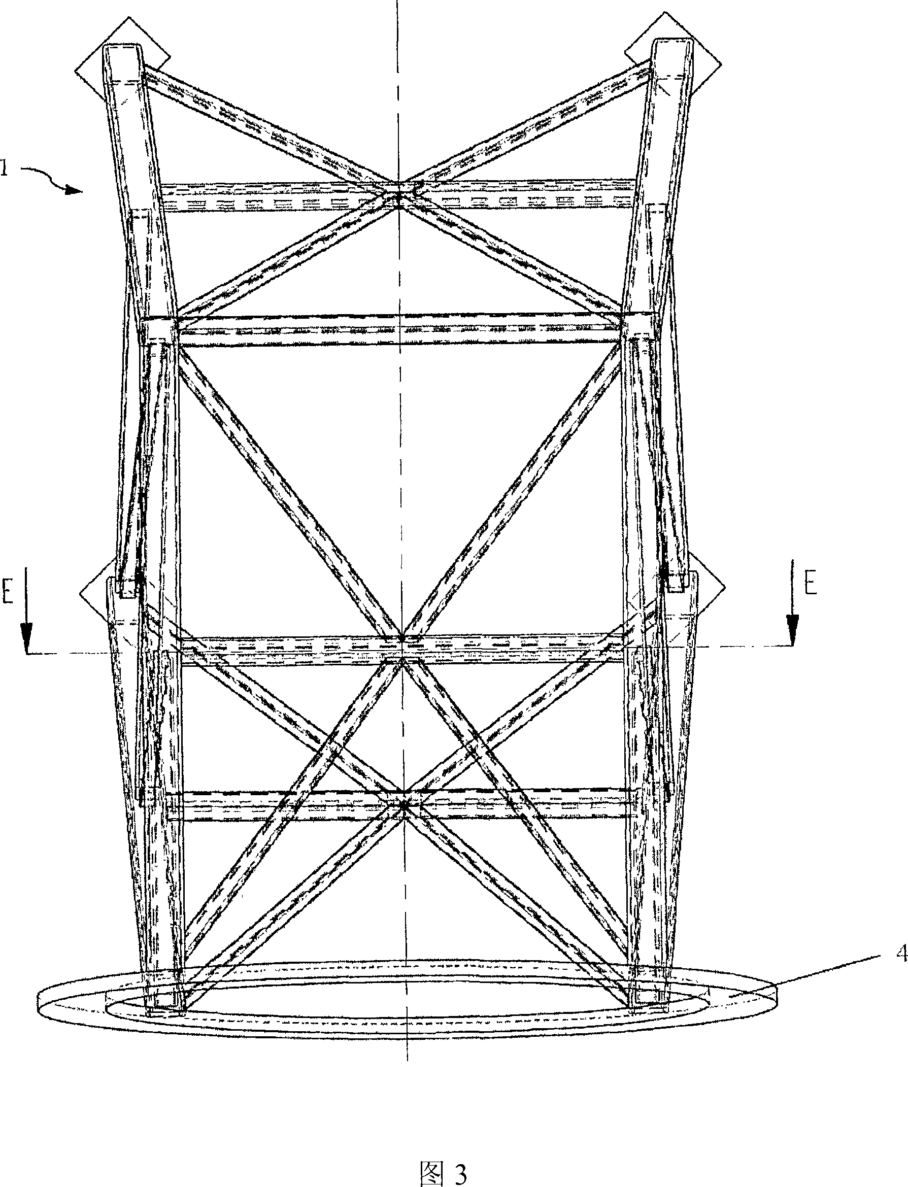
[0056] Figure 1 shows an isometric view of the truss structure of a car 1 according to the present invention. The truss structure consists of rods 2 which form nodes 3 at intersections. Its closing end is formed by a ring 4 in the direction of the rotor sleeve, not shown in the figure. On the side facing away from the ring 4 , the vertical load is distributed via the car-side coupling point 5 . The advantage of the truss member is: due to its versatility, it can provide a very wide variety of possible ways for the car 1 of the present invention, and can be stacked without any problem (unlike the "fishing technique" in toys of the prior art). "Contrast) for expansion.
[0057] 2 and 3 show front and top views of the truss structure of the car 1 of the present invention. It is obvious that the ring 4 does not have to be vertically oriented, but can also be arranged somewhat obliquely (inclined with respect to the rotor). Detailed views in X and Y and a section rotated onto t...
PUM
 Abstract
Description
Claims
Application Information
 - R&D
- Intellectual Property
- Life Sciences
- Materials
- Tech Scout
- Unparalleled Data Quality
- Higher Quality Content
- 60% Fewer Hallucinations
Browse by: Latest US Patents, China's latest patents, Technical Efficacy Thesaurus, Application Domain, Technology Topic, Popular Technical Reports.
© 2025 PatSnap. All rights reserved.Legal|Privacy policy|Modern Slavery Act Transparency Statement|Sitemap|About US| Contact US: help@patsnap.com


