


Quick Research
Generate reliable direction feasibility study reports for your R&D in just a few steps.

Technical Q&A
Discover and master advanced knowledge NOW. Basics, ideas, possibilities, all at once.

Find Solutions
As an expert in R&D theories, this can generate solutions to your technical problems instantly.

Evaluate Feasibility
Analyze your overall solution with one click, know your potential R&D risks in advance.

Monitor Landscape
Get weekly tech updates, stay abreast of the latest tech innovations and key insights.
Vaporizer, fuel cell having vaporizer, and vaporizing method
A gasification device, technology in the thickness direction, applied in the field of gasification devices, can solve the problems of unstable power generation performance of modified fuel cells, overheating of fuel, etc., easy mixing of liquid droplets, etc.
- Summary
- Abstract
- Description
- Claims
- Application Information
AI Technical Summary
Problems solved by technology
Method used
Image

Examples
no. 1 Embodiment approach
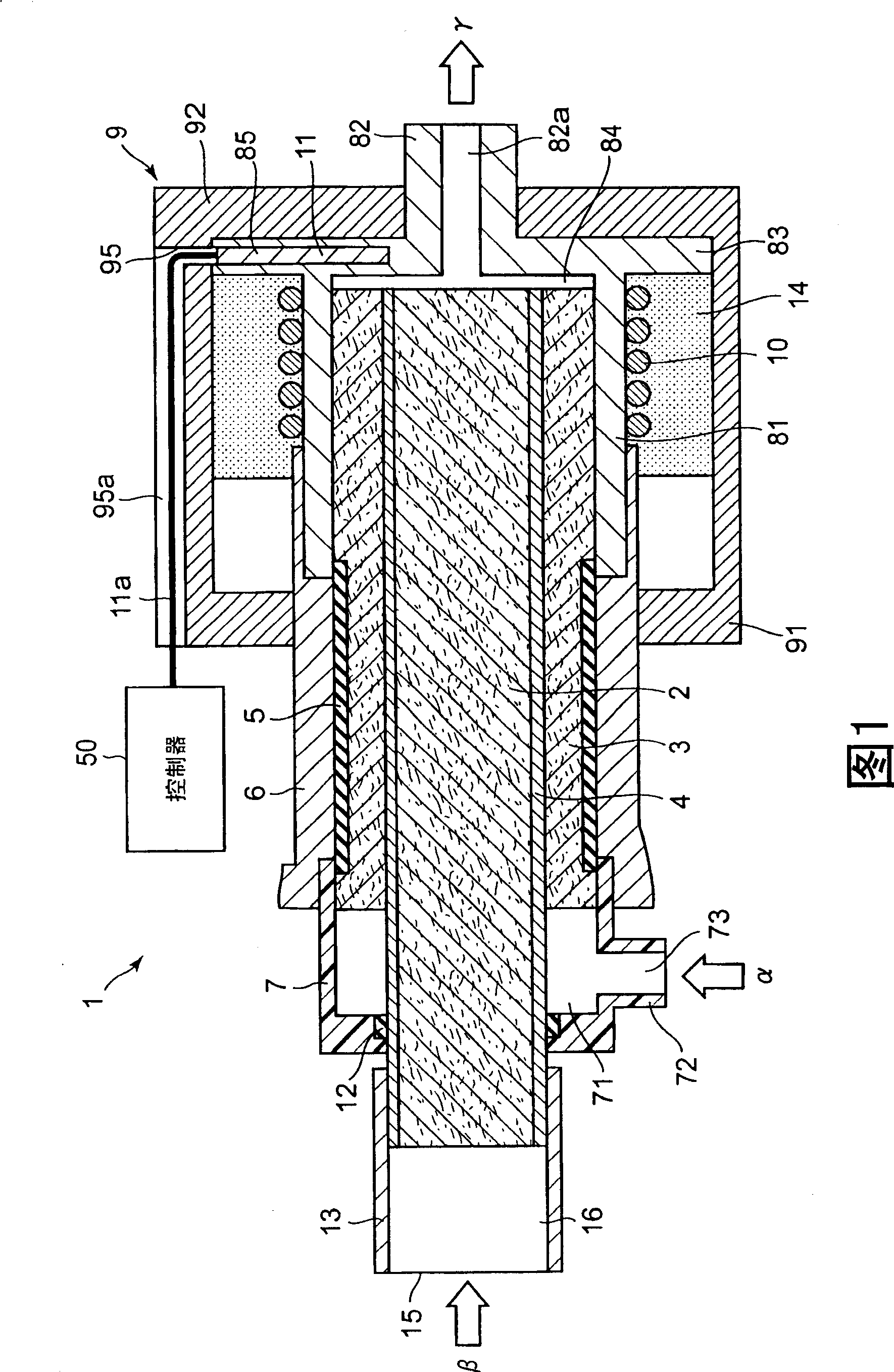
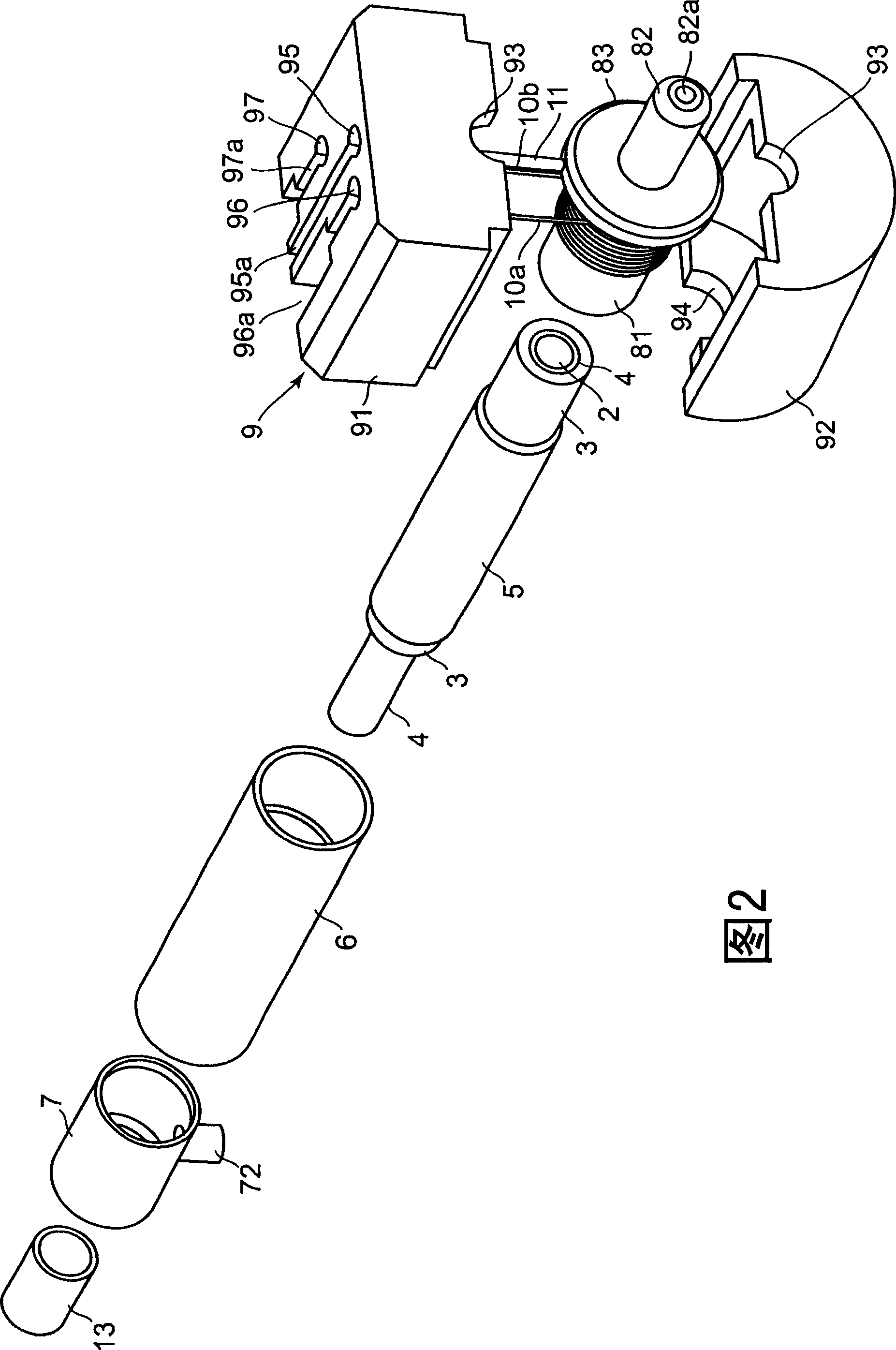
[0055] figure 1 is a schematic sectional view of the gasification device 1, figure 2 It is an exploded perspective view showing the top, front and right sides of the gasification device 1 .
[0056] Such as figure 1 , figure 2 As shown, the vaporization device 1 includes a first liquid suction part 3, a second liquid suction part 2, a partition part 4, a shrinkable tube 5, an elastic tube 6, a first liquid introduction part 7, a second liquid introduction part 13, Discharge unit 8 , heat insulation box 9 , heating element 10 and temperature sensor 11 .
[0057] The second liquid absorbing part 2 is a rod-shaped, more specifically, a cylindrical core material. The second liquid absorbing portion 2 is a porous body having minute spaces formed inside, and is a member capable of absorbing liquid by capillary action. The second liquid-absorbing part 2 is formed by fixing inorganic fibers or organic fibers through a binding material (such as epoxy resin), or sintering inorgan...
no. 2 Embodiment approach
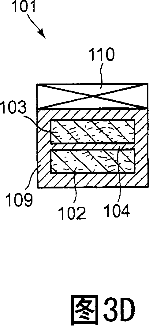
[0105] Figure 3A is a rear view of the gasification device 101, Figure 3B is along Figure 3A A cross-sectional view of the plane of the cutting line B-B shown, Figure 3C is a front view of the gasification device 101, Figure 3D is along Figure 3B A cross-sectional view taken along the plane of the cutting line D-D shown.
[0106] Such as Figure 3A ~ Figure 3D As shown, the main body pipe 109 is provided in a square pipe shape, the rear opening and the front opening of the main body pipe 109 are closed, and an inner space is formed in the main body pipe 109 . A partition wall 104 parallel to its upper and lower surfaces is formed inside the main pipe 109 , and the internal space of the main pipe 109 is divided by the partition wall 104 into two upper and lower spaces from the front to the rear of the main pipe 109 . In addition, the partition wall 104 is connected to the inner side of the rear end surface and the left and right side surfaces of the main body pipe 1...
Embodiment 1
[0142] undergone an experiment. In the experiment, use Figure 5 A gasification device 501 as shown is used as a comparative example. The gasification device 501 is to figure 1 The partition part 4, the first liquid absorption part 3 and the second liquid absorption part 2 are replaced by a single cylindrical liquid absorption part 502, the elastic tube 6 is lengthened, and the first liquid introduction part is removed. Except for the above, the gasification device 501 is the same as the gasification device 1, and the pump is connected to the flow meter, the flow meter is connected to the elastic tube 6, and the discharge hole 82a of the discharge port 82 is opened. In addition, the conditions of the liquid absorption part 502 are as follows.
[0143] (a) Liquid absorbing part 502 (cylindrical body): porosity 41%, particle diameter 30 μm, diameter 1.5 mm, length 10.0 mm, and the tip 2 mm is heated to 130° C. through the heating element 10 via the housing portion 81 .
[01...
PUM
| Property | Measurement | Unit |
|---|---|---|
| boiling point | aaaaa | aaaaa |
| boiling point | aaaaa | aaaaa |
| particle diameter | aaaaa | aaaaa |
Abstract
Description
Claims
Application Information
 - R&D Engineer
- R&D Manager
- IP Professional
- Industry Leading Data Capabilities
- Powerful AI technology
- Patent DNA Extraction
Browse by: Latest US Patents, China's latest patents, Technical Efficacy Thesaurus, Application Domain, Technology Topic, Popular Technical Reports.
© 2024 PatSnap. All rights reserved.Legal|Privacy policy|Modern Slavery Act Transparency Statement|Sitemap|About US| Contact US: help@patsnap.com